Did not you find what you were looking for? Ask us! We have archives of 140 TB. We have all modern reuse projects and renovation projects for Soviet standard buildings. Write to us: info@proekt.sx
Gas station project for 500 orders/day

Project documentation without estimates and results of engineering surveys for the construction of a gas station
Technical and economic indicators
Plot area, ha: 0,5
total building area
including: m2: 643,0
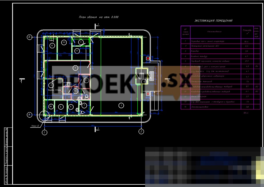
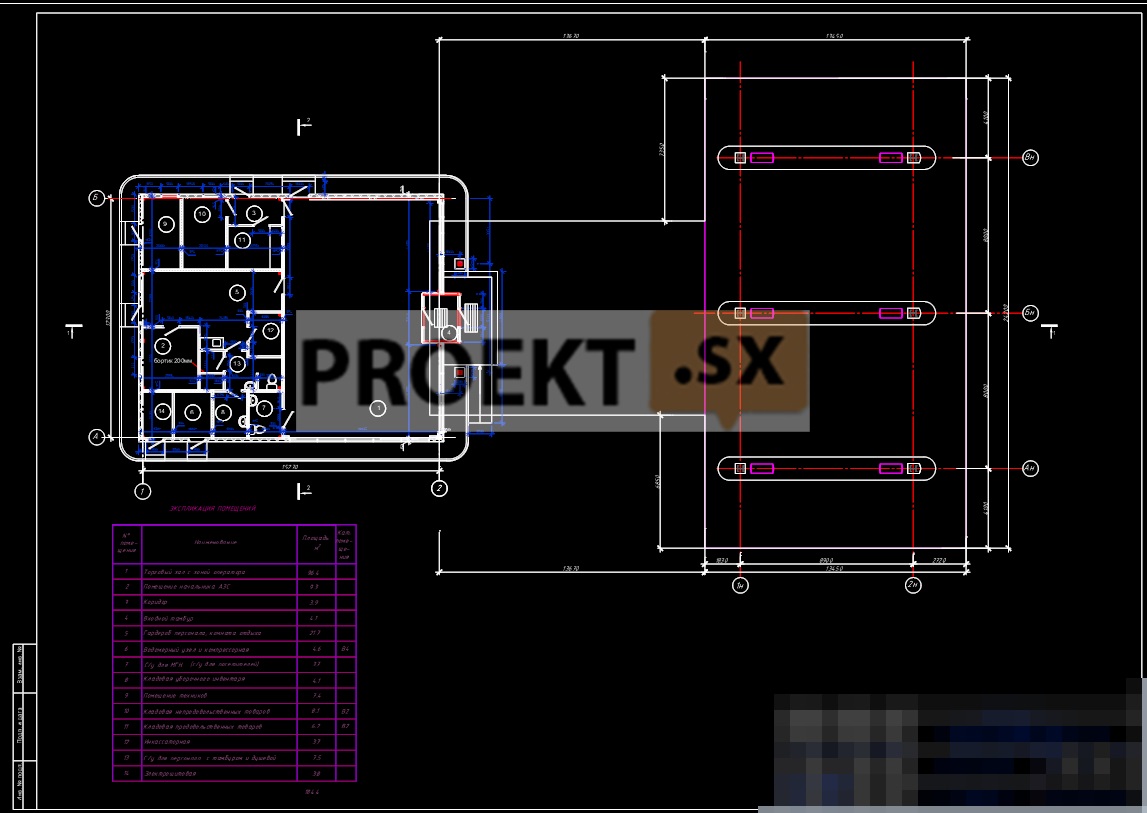
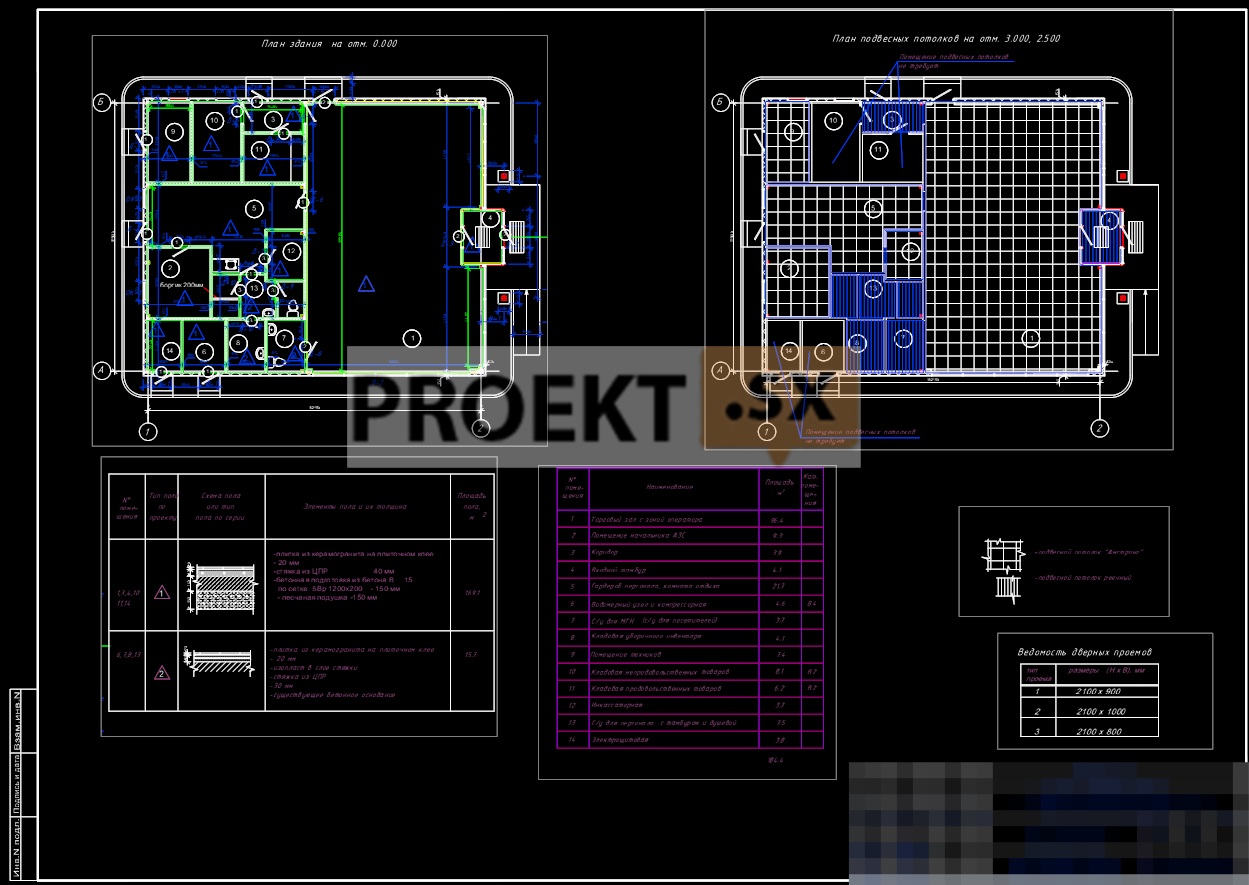
control room building, m2: 201,0
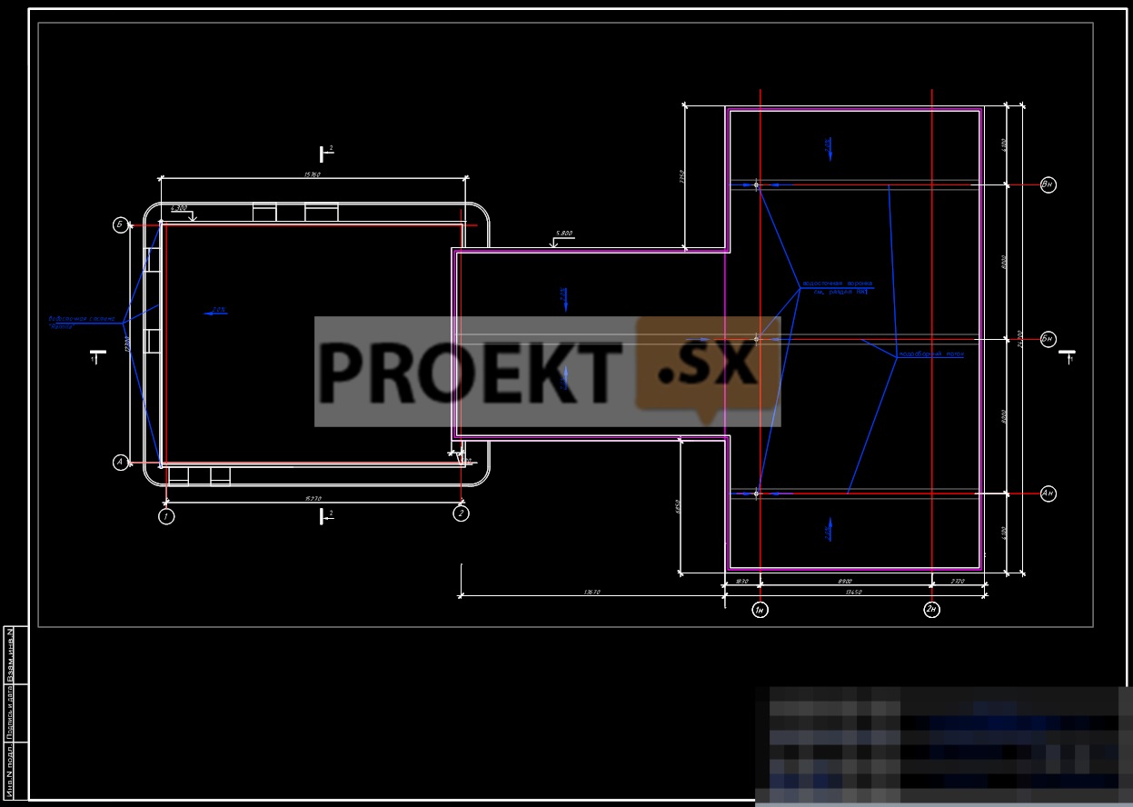
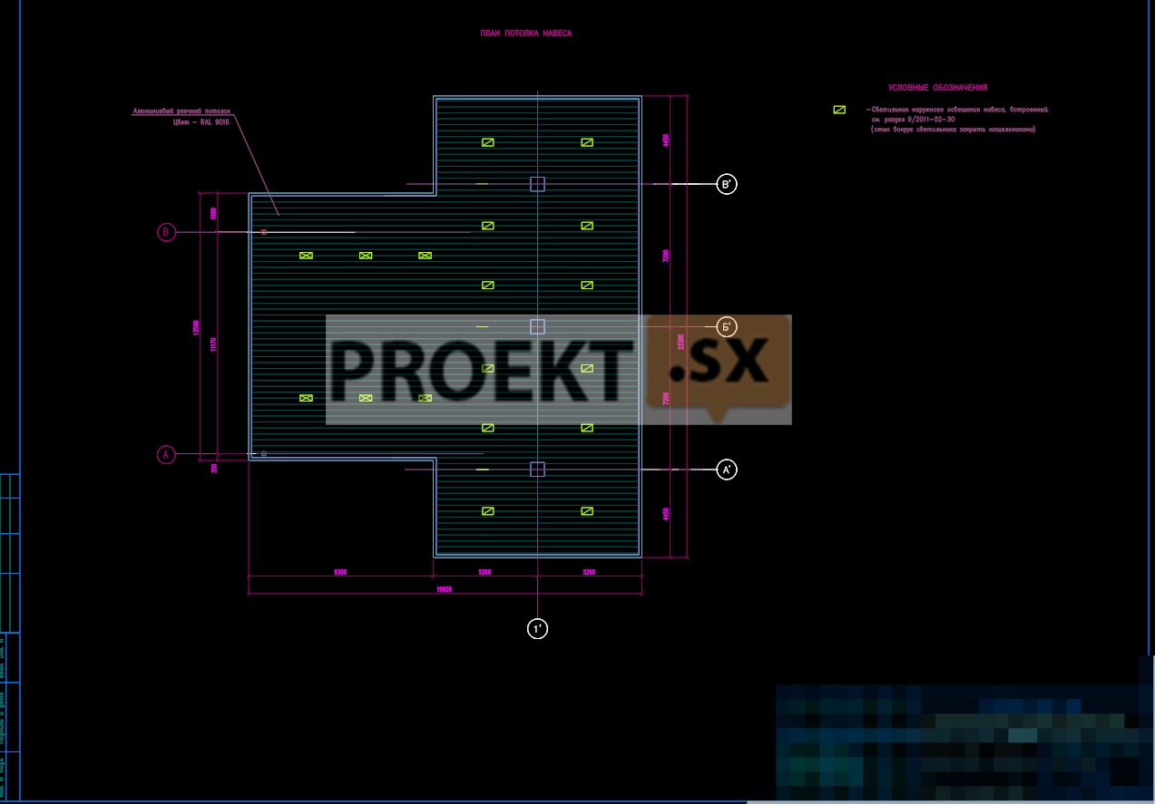
canopy, m2: 442,0
Total area of the control room building, m2: 184,4
Construction volume of the control room building, m3: 864,3
Architectural and space-planning solutions
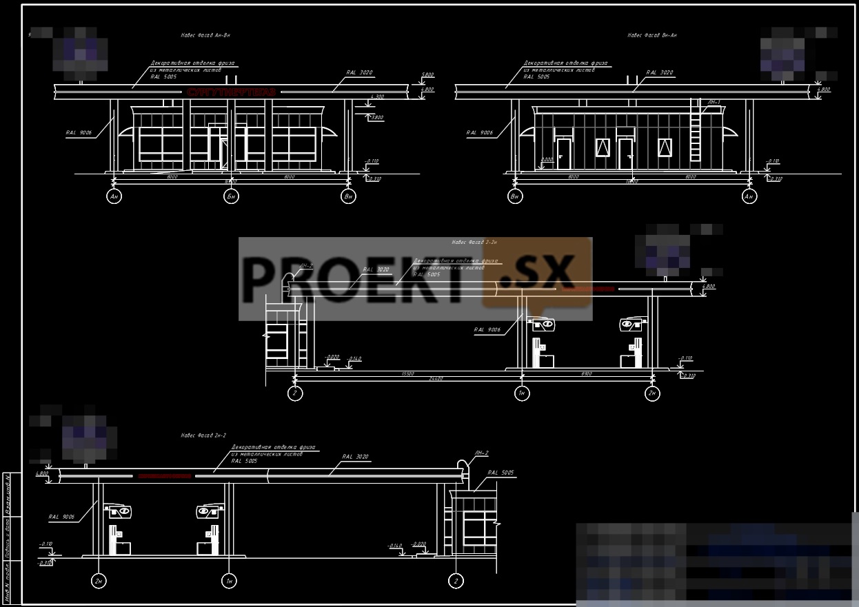
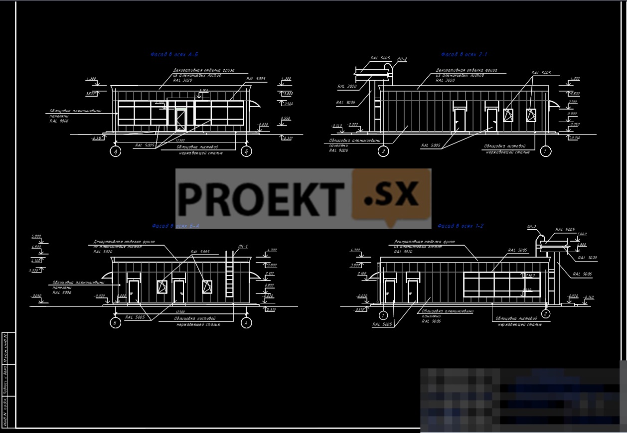
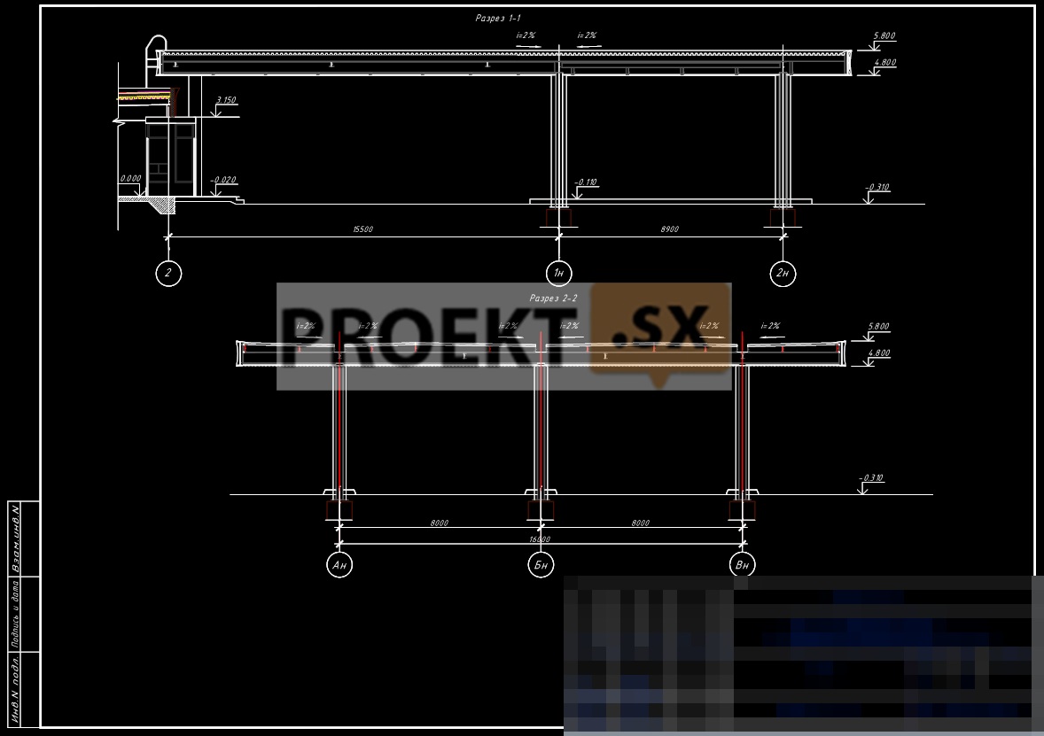
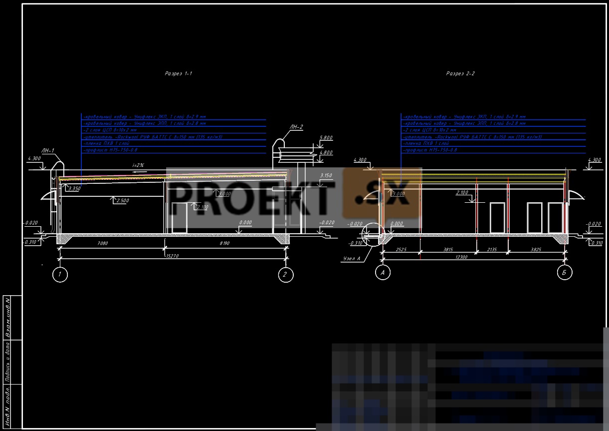
The project documentation provides for the construction of a stationary filling station with an operator building and a canopy over fuel dispensers. The building of the control room and the canopy over the fuel dispensers are the components of the filling station designed for refueling cars and trucks, as well as servicing drivers and passengers. The control room building is one-story, frame, without a basement or an attic, rectangular in plan, with dimensions in the extreme axes of 15,27 x 12,30 m. The greatest height of the vertical plane of the facade from the planning ground level (-0,310 m) to the top of the parapet is 4,61 m. The height of the premises to the bottom of the suspended ceilings is 3,0 m, 2,50 m. The mark of the clean floor of the building is taken as a relative mark of 0,000. The building houses: a trading floor with an operator's area, a chief's room, a rest room and a staff wardrobe, a water metering unit and a compressor room, a pantry for cleaning equipment, a room for technicians, a pantry for food products, a pantry for non-food products, an electrical panel room, a vestibule, corridors, sanitary facilities. The main entrance to the building is designed from the side of the main facade. The main facade of the building is oriented towards the territory of the station. The stained-glass window occupies the main area of the main facade. The frame is metal. Walls - sandwich panels 150 mm thick with mineral wool filling. Partitions - from plasterboard sheets on a metal frame with mineral wool filling, 98 mm and 125 mm thick, in a simple and moisture-resistant design. Stained-glass window, stained-glass windows and doors - made of aluminum profiles with double-glazed windows with a protective film. Window blocks - made of aluminum profiles with double-glazed windows with a protective film. Doors - metal, metal-plastic and wooden, in accordance with GOST and individual production, in the usual and fire-resistant design. The roof is flat, combined, with a roof made of rolled materials (the top layer is with gravel protection) on a profiled steel sheet along girders and beams. The drain is internal. The surface of the outer walls is lined with aluminum panels. The plinth is made of stainless steel sheet. The crowning cornice is made of aluminum sheets. Stained glass, window and door blocks, bindings, frames, plums and fittings are white. The interior decoration of the premises and the floors were designed in accordance with the purpose of the premises and the recommendations of the Corporate Style Book of the consumer brand of the gas station network: floors - with floor ceramic tiles, ceramic granite tiles, TZI linoleum; internal lining of external wall panels - from GKL and GKLV, followed by painting with water-based paint, facing with ceramic tiles or wallpapering; suspended ceilings - from sheets of GKL and GKLV with subsequent water-based painting and slatted. The building's external enclosing structures are adopted on the basis of thermal engineering calculations and comply with the requirements of SNiP 23-02-2003. Premises with permanent residence of people are designed with natural light. A canopy is designed above the fuel dispensers and above the space between the control room building and the fuel dispensers. The canopy over the fuel dispensers is a modular-frame structure, the rectangular projection of which has a plan size of 13,45 x 24,20 m. The highest height from the planning ground level (-0,310 m) to the top of the roof is 6,110 m. The connecting canopy between the control room building and the fuel dispensing islands is a frame-type structure, the rectangular projection of which has a plan size of 14,17x10,00 m. The frame is metal. The roof is flat, with corrugated steel sheet roofing over girders and beams. The drain is internal. Covering the area under the canopy - concrete sparkling and oil-petrol resistant tiles. The finishing material is a smooth metal sheet with a polymer coating. Measures are envisaged to ensure the accessibility of the building and facilities for people with limited mobility. The main entrance-exit to the building is equipped with a ramp. The ramp has a width of 1,20 m, the slope is within 5%, the surface is hard, non-slip. Doorways do not have thresholds. The width of the door panels is assumed to be at least 0,9 m.
Structural and space-planning solutions
The control room and shed buildings are designed in a steel frame. Level of responsibility – II. The spatial immutability of the frame of the control room is ensured by the joint work of the columns, rigidly fixed in the foundation, and the hard disk of the cover. The node supporting the roof beams on the columns is hinged. The rigidity of the coating disc is ensured by fastening the corrugated board to the girders in each wave on the extreme spans and through the wave on the middle spans. The sections of the main load-bearing structures of the frame were adopted: columns - square pipes according to GOST 30245-2003 from steel C245; roof beams - I-beam according to STO ASCHM 20-93 from steel C245, roof decking - H57-750-0.8 according to GOST 24045-94. As external enclosing walls, hinged wall panels of the “sandwich” type 150 mm thick are used, the coating is corrugated board, laid directly on the top of the beam belt. A fachwerk system has been developed for fixing wall panels. The foundation for the control room building is a non-buried monolithic reinforced concrete slab 180 mm thick, with monolithic beams along the contour and under columns 650 mm high, made of B20, W4, F50 class concrete. Under the foundation slab, a complete selection of bulk soil is made, followed by the installation of an artificial foundation. To prevent freezing of the foundation slabs, insulation with Penoplex slabs is provided. The average pressure under the sole of the foundation slab is 1,94 kg/cm2. The design soil resistance of the base is 2,53 kg/cm2. The expected settlement of the foundation slab is 0,3 cm. The spatial invariability of the canopy frame is ensured by the joint operation of the columns, which have a rigid support unit on the foundation, with a hard disk of the profiled flooring, which is fastened with self-tapping screws in each wave. The main roof beams are pivotally supported by columns. The columns and beams of the canopy are designed from I-beams according to STO ASCHM 20-93 from steel C245, corrugated board - H75-750-0.8 according to GOST 24045-94. The foundations for the canopy columns are monolithic reinforced concrete columnar foundations made of concrete B20, W4, F50. In accordance with the report on engineering and geological surveys, the base of the canopy foundation is the EGE-2 layer - heavy silty loam, hard-plastic, which has the following characteristics: e = 0,649; E=110 kg/cm2. The average pressure under the base of the foundation will be 1,05 kg/cm2, the design soil resistance of the base is 2,45 kg/cm2. The expected settlement is 1,7 cm. The foundations of underground tanks are taken on a natural basis in the form of a monolithic reinforced concrete slab 400 mm thick, concrete B20, W4, F50. The basis for the foundations for the tanks is the EGE-3 layer - light silty loam, semi-solid with gravel and pebbles, which has the following characteristics: ρн=2,16 t/m3; Сn=0,4 kg/cm2; e=0,471; E=140 kg/cm2. The design of the foundations provides stability against ascent. All foundations are laid on crushed stone preparation 100 mm thick, spilled with bitumen. The project provides for coating waterproofing of the outer faces of the foundations in contact with the ground. The calculation of the main load-bearing structures of the frames was carried out using the SCAD software package version R11.3. The maximum horizontal movement of the canopy frame is 13,67 mm. The displacements and deflections obtained as a result of the spatial calculation of the building frame do not exceed the allowable values. The relative mark of 0,000 corresponds to the absolute mark of 56.01. 9.2.4. Engineering equipment, engineering and technical support networks, engineering and technical measures: Water supply (cold water supply) to consumers of the facility, in accordance with the UE, it is provided for one projected input of the water supply network with a diameter of D = 63 mm from pressure pipes PE100 SDR17-63x3,8 PN 10 from the designed water supply network along the highway, connected to the existing water supply network D = 300 mm. At the input, a water metering unit is provided according to the TsIRV. Guaranteed pressure at the connection point 20 m of water. Art. Estimated consumption of cold water: for household and drinking needs 0,96 m3/day; for irrigation of the adjacent territory 7,39 m3/day. A drinking water supply system has been designed for the building. The required pressure for the drinking water supply system is 12 m. Internal fire extinguishing of the gas station building is not provided in accordance with clause 6.5a*, table 1* of SNiP 2.04.01-85* and NPB 111-98*, clause 94, Amendment 2. For watering the territory on the outer wall of the building, 1 watering tap D = 25 mm is provided. External fire extinguishing is provided from two designed fire tanks with a volume of 50 m3 each, installed at the gas station site. Water consumption for external fire extinguishing of gas stations is assumed to be 10 l/s in accordance with SNiP 2.04.02-84*. To prepare hot water, a capacitive electric water heater manufactured by KAUKORA VLK100 with a capacity of V = 100 l and a power of N = 2,0 kW is used. The estimated consumption of hot water for household and drinking needs is 0,48 m3 / day. Hot water temperature (Тз) – 65°С. Metal-plastic pipes according to GOST 3262-75 were chosen for the device of the hot water supply system. The following systems are designed for the building: domestic sewerage; outdoor drains. A ladder is provided to remove wastewater from the water metering unit. Pressure sewer pipes PP 100 according to GOST 6942.3-98 were selected for the installation of domestic sewage systems. Pipes of the "Rannila" system were chosen for the construction of the external drainage system. External water supply networks are laid at a depth of 2-3 m. External sewerage networks are laid at a depth of 2,4-1 m. Power supply to electrical receivers of gas stations of all categories in terms of power supply reliability in normal mode, according to the specifications, is provided from the centralized power supply system through one cable gland , in emergency mode - from an autonomous 100 kVA diesel generator, in post-emergency mode - from an autonomous uninterruptible power supply, but only from power receivers of security systems (the first category in terms of power supply reliability). The total rated power of the electrical installation is 85 kVA, including the rated power of electrical receivers of security systems - 4,2 kVA. Grounding system for open conductive parts-TN-S (separate, PE cable conductor of the corresponding power receiver). To ground the neutral of the generator (working zero), an additional charger is provided, the resistance of which is ≤30 Ohm, the resistance of the multifunctional charger is ≤4 Ohm, taking into account natural grounding. Schematic and design solutions of the designed electrical installation ensure the electrical safety of uncategorized and operating personnel (solid insulation, shutdown of non-stationary processes, lack of contact voltage, etc.), grounding and potential equalization systems are designed in accordance with the standards. Providing the facility with telephone communication is provided through the use of mobile communications. The heat carrier for the heating system is water with a temperature of 80-60 ° C. The heating system is a two-pipe horizontal radiator with a dead-end movement of the coolant. Heating devices - panel radiators and convectors (for the trading floor). To balance the heating system, automatic valves of the Danfoss type are installed. Metal-plastic pipes were chosen for the installation of heating systems. Ventilation - forced-air and exhaust with mechanical and natural motivation. The air flow rates for the premises are determined according to the sanitary norm and the air exchange rate. A unit with heat recovery is provided for the trading floor and staff amenity premises. Removal of air from the bathrooms and pantry of cleaning equipment is carried out by an independent exhaust system. Placement of equipment - behind the suspended ceiling of the serviced premises. Ventilation of technical and utility rooms is natural. To remove excess heat during the warm season, air conditioning systems were designed with the installation of ceiling-type indoor units for the trading floor (split system), as well as for administrative and amenity premises (multi-split systems). The placement of outdoor units is provided on the facade of the building.