Did not you find what you were looking for? Ask us! We have archives of 140 TB. We have all modern reuse projects and renovation projects for Soviet standard buildings. Write to us: info@proekt.sx
Project of an apartment building 12,15,18,19 floors


Design documentation, including estimates, and the results of engineering surveys for the construction of apartment buildings bldg. 12, 14, 26.
Technical and economic characteristics of the capital construction object
Plot area, ha: 6,4663
Building 12
Building area, m2: 4523,0
Total building area, m2: 57221,66
Construction volume of the building, m3: 194993,99
Total area of apartments (including loggias, balconies), m2: 41097.07
Number of apartments, including: pcs.: 698
1-room apartments, pcs.: 330
2-room apartments, pcs.: 181
3-room apartments, pcs.: 160
4-room apartments, pcs.: 24
5-room apartments, pcs.: 3
Floors, including the upper technical floor, floor: 12, 15, 18, 19
Building 14
Building area, m2: 3065,0
Total building area, m2: 47820,66
Construction volume of the building, m3: 156088,58
Total area of apartments (including loggias, balconies), m2: 35123,65
Number of apartments, including: pcs.: 585
1-room apartments, pcs.: 263
2-room apartments, pcs.: 161
3-room apartments, pcs.: 139
4-room apartments, pcs.: 22
Floors, including the upper technical floor, floor: 19
Building 26
Building area, m2: 3265,0
Total building area, m2: 49330,58
Construction volume of the building, m3: 164075,22
Total area of apartments (including loggias, balconies), m2: 36066,93
Number of apartments, including: pcs.: 576
1-room apartments, pcs.: 244
2-room apartments, pcs.: 138
3-room apartments, pcs.: 156
4-room apartments, pcs.: 36
5-room apartments, pcs.: 2
Floors, including the upper technical floor, floor: 18, 19
Estimated cost at the 2001 base price level (without VAT)
Total: thousand rubles: 811
Construction and installation works, thousand rubles: 708
Equipment, thousand rubles: 32
Other expenses, thousand rubles: 70
including: - -
PIR, thousand rubles: 40457,43
refundable amounts, thousand rubles: 1
In addition, reserve pipes, thousand rubles: 13,58
Estimated cost at the current price level May 2011 (VAT included)
Total: thousand rubles: 4
Construction and installation works, thousand rubles: 4
Equipment
Architectural and space-planning solutions
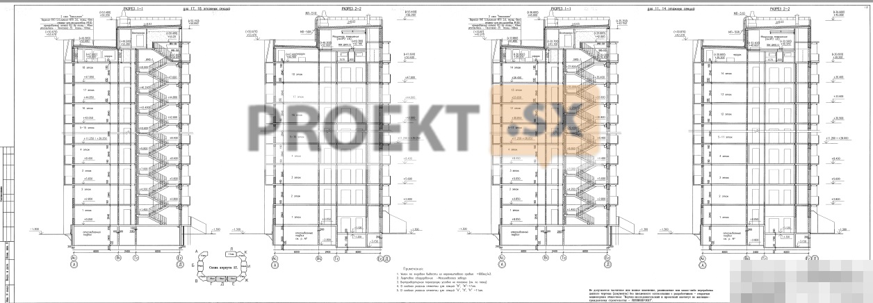
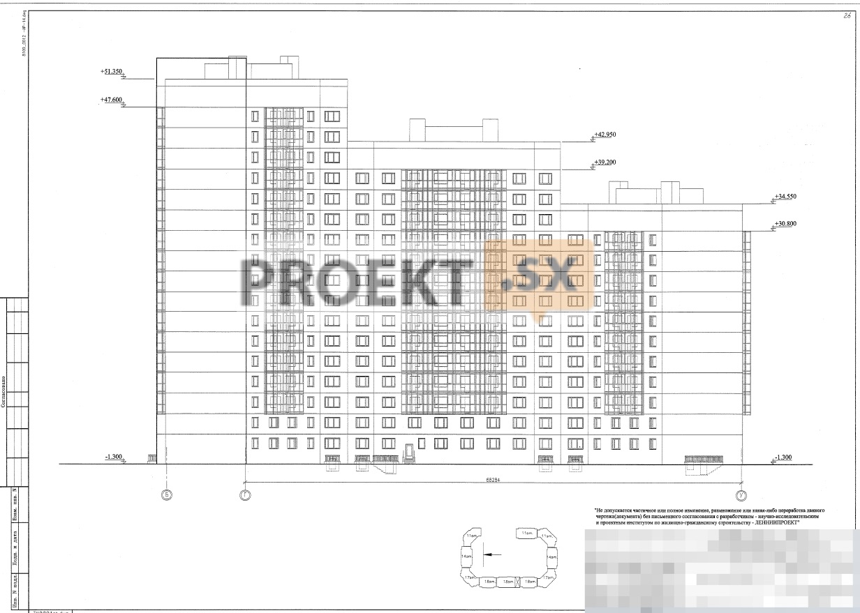
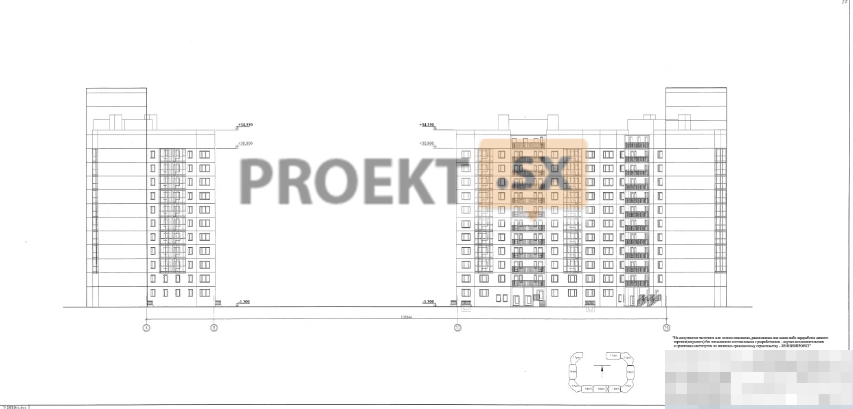
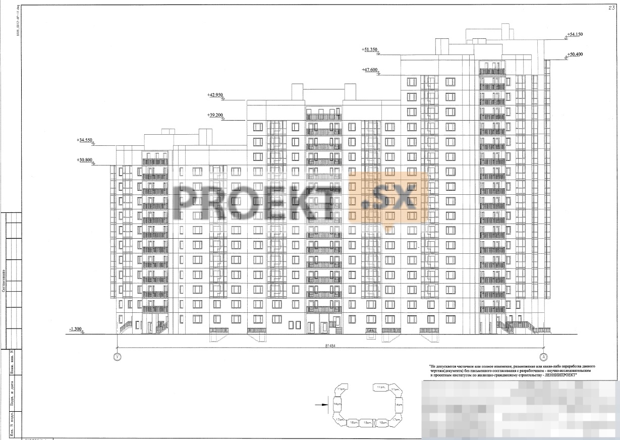
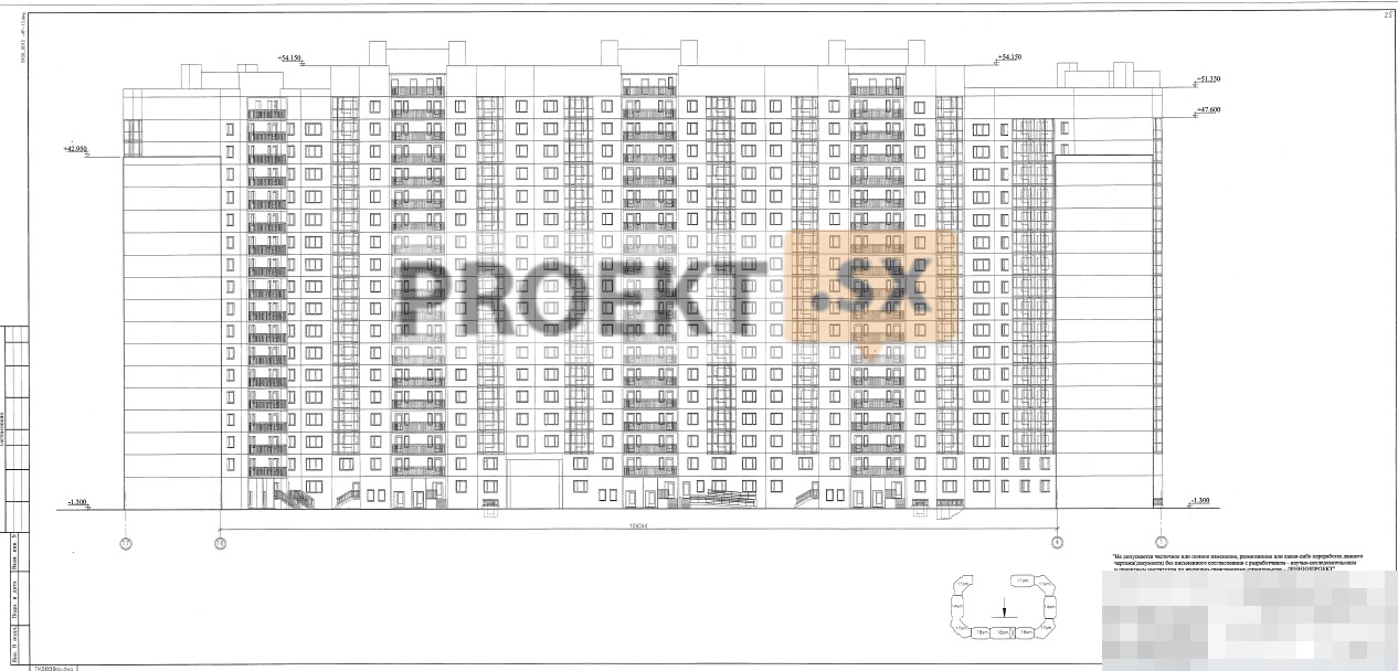
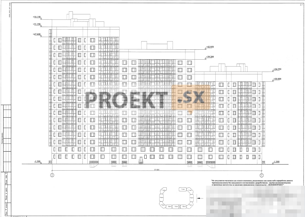
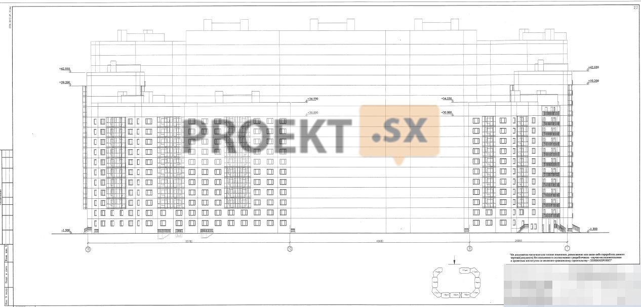
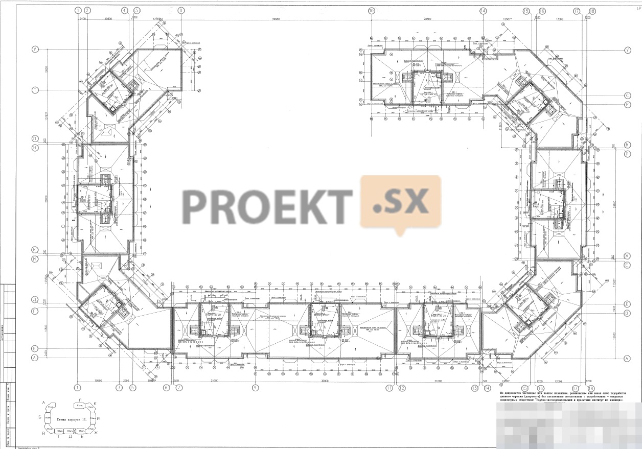
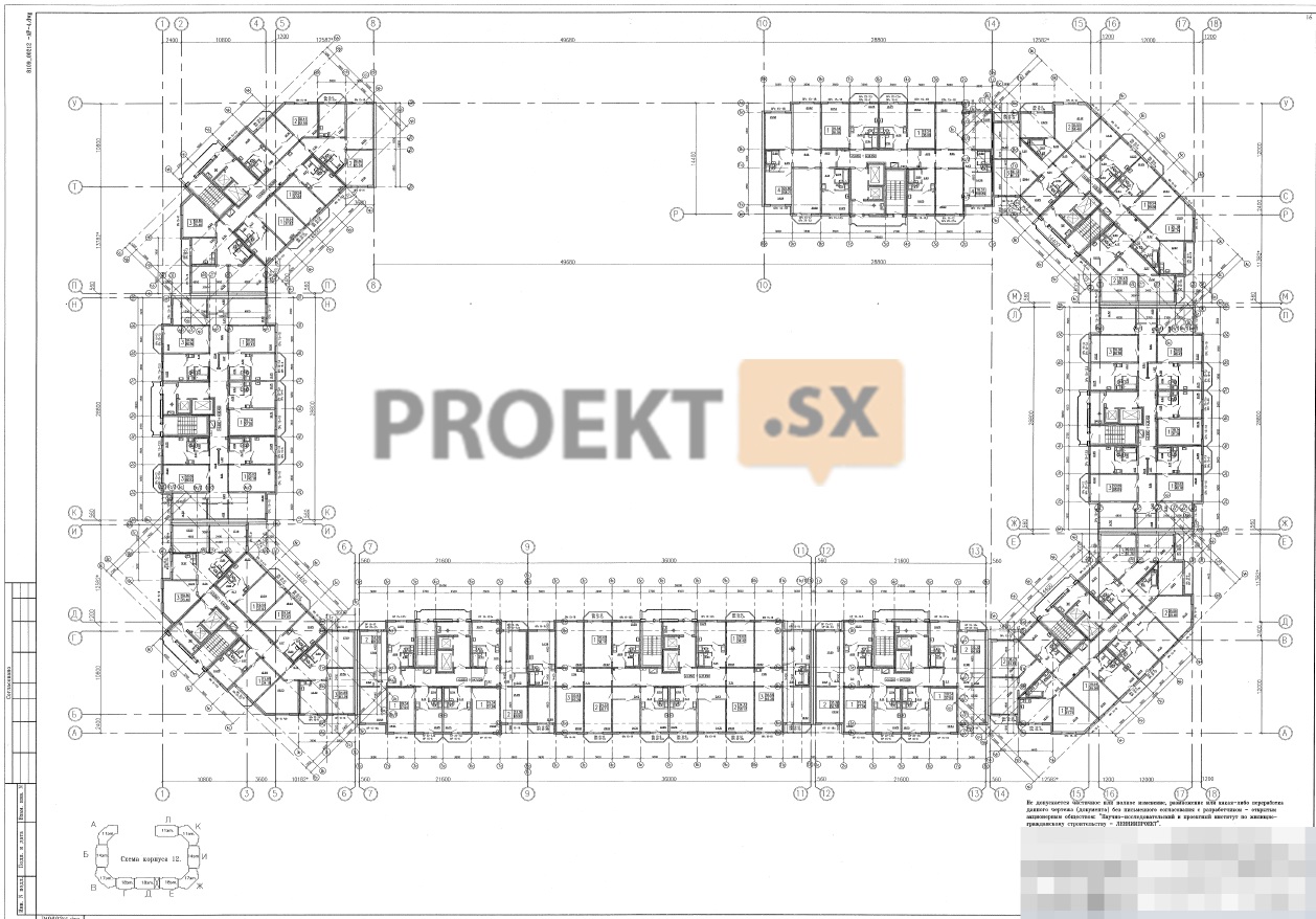
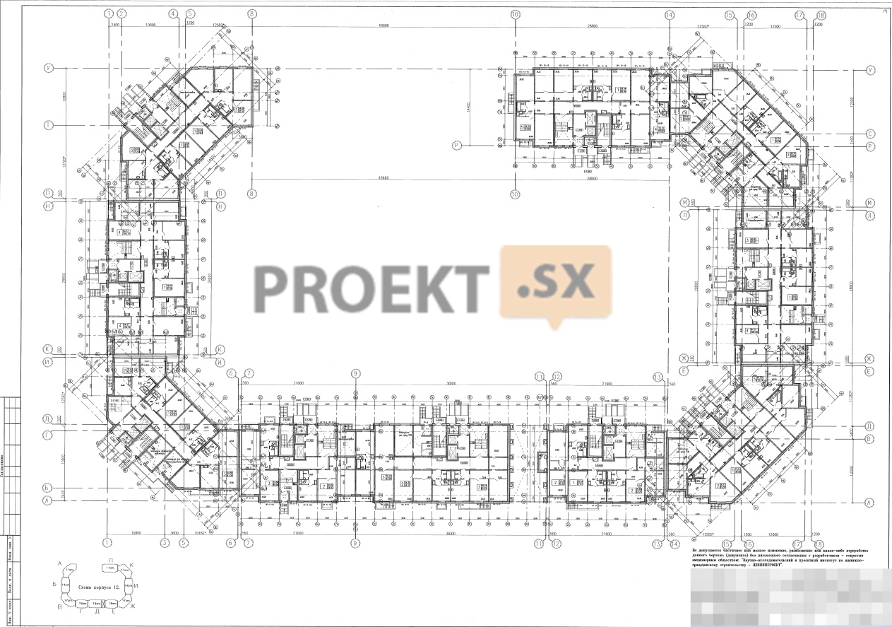
Design documentation has been developed for the construction of 3 residential buildings: building 12, building 14 and building 26. Building 12 is an apartment building with a basement and a technical attic, consists of 10 sections, has a C-shaped outline in plan, a through passage for fire trucks in the central part along the long side of the building and 3 through passages at the level of the 1st floor. The number of floors of a residential building (including the upper technical floor (attic) in each section) decreases from 19 floors in the central part to 12 floors along the edges of the building (19, 18, 15, 12. For a relative mark of 0,000, the level of the top of the basement floor slab was taken. The height of the residential floors is assumed to be 2,8 m, the height of the basement floor is 2,8 m, the height of the technical attic rooms is variable: from 1,7 m to 1,9 m. The maximum height of the vertical plane of the facade from the planning ground level to the top of the parapet of the protruding elements of the building is 57,5 m. Residential apartments are designed from the 1st to the 11th, 14th, 17th, 18th floors inclusive. On the first floor, the premises of the HOA are designed. In the basement of the building, rooms for utility pumping stations, a fire pumping station, water metering units, individual heating points, cable entry rooms, ventilation chambers are designed, and engineering communications are provided. In the technical attic of the building, rooms for ventilation chambers are designed and wiring of engineering communications is provided. Each section has an independent entrance leading to the vestibule and is equipped with 2 elevators with a carrying capacity of 400 kg and 630 kg, the machine rooms of the elevators protrude above the roof plane. Building 14 - a multi-apartment 19-storey (including the upper technical attic) residential building with a basement and a technical attic, consisting of 6 sections, having an L-shaped outline in plan, 2 through passages at the level of the 1st floor. For a relative mark of 0,000, the level of the top of the basement floor slab was taken. The height of the residential floors is assumed to be 2,8 m, the height of the basement floor is 2,8 m, the height of the technical attic rooms is variable: from 1,7 m to 1,9 m. The maximum height of the vertical plane of the facade from the planning level of the ground to the top of the parapet of the protruding elements of the building is 57,5 m. Residential apartments are designed from the 1st to the 18th floors inclusive. On the first floor, the premises of the HOA are designed. In the basement of the building, the premises of the utility pumping station, fire pumping station, water metering unit, individual heating point, cable entry room are designed, engineering communications are provided. In the technical attic of the building, rooms for ventilation chambers are designed and wiring of engineering communications is provided. Each section has its own entrance leading to the lobby and is equipped with 2 lifts with a capacity of 400 kg and 630 kg. Machine rooms protrude above the plane of the roofs. Building 26 - multi-apartment 18-19-storey (including the upper technical attic) residential building with a basement and a technical attic, consisting of 7 sections, having an L-shaped outline in plan, 2 through passages at the level of the 1st floor. For a relative mark of 0,000, the level of the top of the basement floor slab was taken. The height of the residential floors is assumed to be 2,8 m, the height of the basement floor in sections B and C is 3,45 m, in the remaining sections - 2,8 m, the height of the technical attic rooms is variable: from 1,7 m to 1,9 m. The maximum height of the vertical plane of the facade from the planning level of the ground to the top of the parapet of the protruding elements of the building is 57,5 m. Residential apartments are designed from the 1st to the 17th-18th floors inclusive. On the first floor, the premises of the HOA are designed. In the basement of the building, the premises of the utility pumping station, fire pumping station, water metering unit, individual heating point, cable entry room are designed, engineering communications are provided. In the technical attic of the building, rooms for ventilation chambers are designed and wiring of engineering communications is provided. Each section has its own entrance leading to the lobby and is equipped with 2 lifts with a capacity of 400 kg and 630 kg. Machine rooms protrude above the plane of the roofs. In each section of each residential building for evacuation and communication between floors, non-smokeable staircases H1 are designed (exit to the staircase from the floor through the outer air zone). Independent exits are designed from each basement compartment of each residential building. Exits to the roof are provided through the stairwells. Metal vertical ladders are installed in places where the heights of the roof vary.
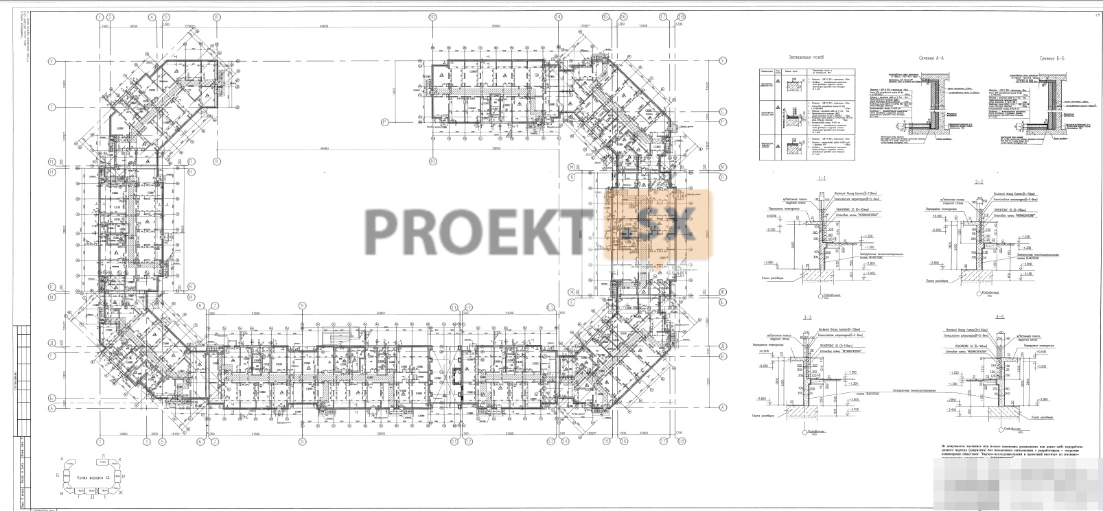
Structural and space-planning solutions
Building responsibility level – II (normal). Multi-apartment residential buildings are designed from three separate residential buildings (building 12, 14, 26). Sections of high-rise buildings are separated from each other by temperature-settlement seams. The structural scheme of multi-storey panel buildings is a cross-wall system of products of the 137th series, produced by CJSC DSK "BLOK", with wall structures and basement ceilings made of monolithic reinforced concrete. Bearing external walls - single-layer reinforced concrete panels 160 mm thick (concrete B22,5, B15, F50) with facade insulation (insulation thickness 150 mm) and plastering. Bearing external walls in expansion joints - three-layer reinforced concrete panels with flexible connections, made of concrete B22,5 and B15, F75, with a total thickness of 420 mm (in the attic 350 mm thick), with an average layer of insulation made of expanded polystyrene with a density of 50 kg / m³, a thickness of 200 mm. The junction of the outer walls is closed. Non-bearing external walls - reinforced concrete hinged panels 120 mm thick (concrete B15, F50) with facade insulation (insulation thickness 150 mm) and plastering. External walls in the basement - from monolithic reinforced concrete B25, W6, F100, below the blind area - 300 mm thick with foam insulation (layer thickness 50 mm), above the blind area - 160 mm thick with foam insulation 100 mm thick and finished with Melikonpolar concrete stone 120 mm. Internal walls - prefabricated reinforced concrete panels made of B15 and B22,5 concrete 160 mm thick, in the basement - made of monolithic reinforced concrete 200 mm thick (concrete B25, W6, F100). Ceilings - prefabricated reinforced concrete slabs 160 mm thick made of B15 concrete with support on three and two sides, above the basement - made of monolithic reinforced concrete B25, F50, 200 mm thick. Overlapping over the passage - slabs of monolithic reinforced concrete along the beams, installed on monolithic reinforced concrete columns with a section of 400x600mm. Concrete B25, W6, F100. Balcony slabs - prefabricated reinforced concrete 160 mm thick from concrete B22,5, W2, F75, combined with a floor slab, in the area of passage through the outer walls - with thermal breaks. Elevator shafts (wall thickness 120 mm), ventilation units, sanitary cabins, lintels - prefabricated reinforced concrete. Stairs - from prefabricated reinforced concrete marching platforms. The structures of the pits, porches and ramps are made of monolithic reinforced concrete. Interfacing of load-bearing panels and floor slabs is a platform joint with the transfer of forces to the underlying floor through the floor slab. Fastening of all prefabricated structures to each other - by welding. The spatial rigidity and stability of the building is ensured by the joint work of the transverse and longitudinal walls in combination with floor disks. All prefabricated elements produced by CJSC DSK "BLOK" correspond to the loads of an individual house. Building responsibility level - II. Calculations were made by LenNIIproekt OJSC using the equivalent replacement method, taking into account the joint work of the above-ground part of the building and foundations according to the Lira 9.6 program. For the mark of 0,000 m, the mark of the top of the reinforced concrete floor slab of the first floor in the residential sections was taken, corresponding to the absolute mark of 14.70 (building 14), 15.40 (building 12), 15.70 (building 26). The foundations for all buildings are piled. Grills of buildings - slabs of monolithic reinforced concrete 600 mm thick (concrete B25, F100, W6). Preparation for grillages - from concrete B7,5 with a thickness of 100 mm. Piles in buildings - prefabricated reinforced concrete, composite, section 40x40 cm, length 23 m (12 + 11) and 24 m (12 + 12 for building 26), made of concrete B25, F100, W8. The absolute mark of the bottom of the piles is minus 10.55 (building 12), 11.25 (building 14), 11.00 and 11.25 (building 26). The designed pile field provides for the use of previously made piles (new piles are similar to previously made piles). Based on the results of soil testing with piles, the design load on the pile, assumed to be 80 tf, has not been confirmed. The connection of piles with grillage is rigid. The pile driving method is driving from the bottom of the pit (taking into account the order in which the neighboring sections are erected). The design documentation provides for the testing of piles. In accordance with the report on engineering and geological surveys, it was accepted: The base of the piles of building 12 is light, silty, refractory loam with lenses of sand, gravel and pebbles with E=120 kg/cm2, φn=23°, e=0,557, IL=0,31, silty plastic sandy loam with interlayers of sand with Е=100 kg/cm2, φн=22°, е=0,665, IL=0,52, gravelly dense sand with Е=410 kg/cm2, φн=40°, е=0,54 , light silty clay, semi-solid with fragments of sandstone, layered with Е=130kg/cm2, φн=14°, е=0,645, IL=0,04; the base of the piles of building 14 - light silty soft-plastic loam with sand lenses, gravel and pebbles with E = 110 kg / cm2, φn = 23 °, e = 0,586, IL = 0,34, silty plastic sandy loam with sand interlayers with E = 100 kg /cm2, φn = 22 °, e = 0,652, IL = 0,58, silty dense sand with E = 170 kg/cm2, φn = 29 °, e = 0,59; base of piles of building 26 – light silty, semi-hard clay with sandstone fragments, layered, dislocated with Е = 120 kg/cm2, φн = 15 °, е = 0,638, IL = 0,08 and light silty clay, hard with sandstone fragments, layered with E = 170 kg/cm2, φn = 19°, e = 0,543, IL = -0,16. At the time of the start of the examination, the construction of buildings was already underway, and precipitation during the construction period was not monitored. In addition, the expertise considered the results of observations of the deformations of the foundations of the constructed buildings. According to the results of observations, significant uneven precipitation was not recorded. To assess the general situation in terms of deformations of the foundation of buildings, measurements of the rolls of the constructed buildings were carried out. The actual values of rolls are less than the allowable values indicated in Table. 4.1 TSN 50-302-2004.