Did not you find what you were looking for? Ask us! We have archives of 140 TB. We have all modern reuse projects and renovation projects for Soviet standard buildings. Write to us: info@proekt.sx
Substation project 220 kV


Plot area, ha: 0,6429
Building area of PS 220, m2: 1077,6
Building area, checkpoint, m2: 57,1
Total area of Substation 220, m2: 3348,5
Total area, checkpoint, m2: 63,1
Construction volume PS 220, 19445,3
Building volume through passage, m3: 262,7
including:
above 0,000, PS 220, m3: 16858,9
above 0,000, through passage, m3: 173,4
below 0,000, PS 220, m3: 2586,4
below 0,000, through passage, m3: 89,3
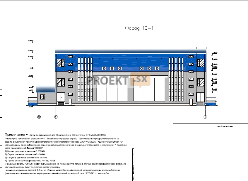
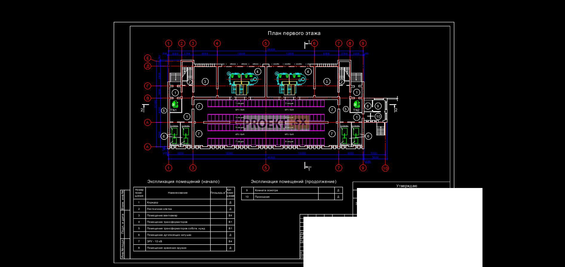
Architectural and space-planning solutions
The project for the reconstruction of the existing building of the 220kV substation provides for the reconstruction and technical re-equipment with the corresponding internal redevelopment. There are 2 staircases in the building, which have access to the 3rd floor and attic and access to the roof through the hatch. The project provides for the following types of work: roof reconstruction - on the existing flat roof along a monolithic belt, metal trusses are mounted with a profiled steel sheet coating along the girders of thin-walled profiles; installation of hinged ventilated facades with additional insulation on existing brick walls; installation of new partitions with plasterboard sheathing on the frame filled with mineral wool. Moisture-resistant plasterboard sheets are provided in wet rooms; increasing window openings to increase natural light; replacement of existing reinforced concrete lintels with metal lintels made of rolled metal; replacement of window blocks with window blocks with double-glazed windows; the reconstruction of metal gates to the premises of transformers is envisaged; the windows of the technical premises of the first and second floors are laid with bricks; doors to fire-hazardous premises are assumed by the project to be steel with a fire resistance limit of 45 minutes; extension of the checkpoint along axis 9 - checkpoint. The checkpoint includes: a security room with a weapon storage room, a bathroom. The extension has a technical basement with an entrance for maintenance of communications. In the basement rooms, in the technical rooms of the first and second floors, the existing floor structures are preserved, in the administrative rooms of the third floor, linoleum is provided, in the corridors and sanitary facilities - ceramic tiles. Interior decoration is provided in accordance with the purpose of the premises.
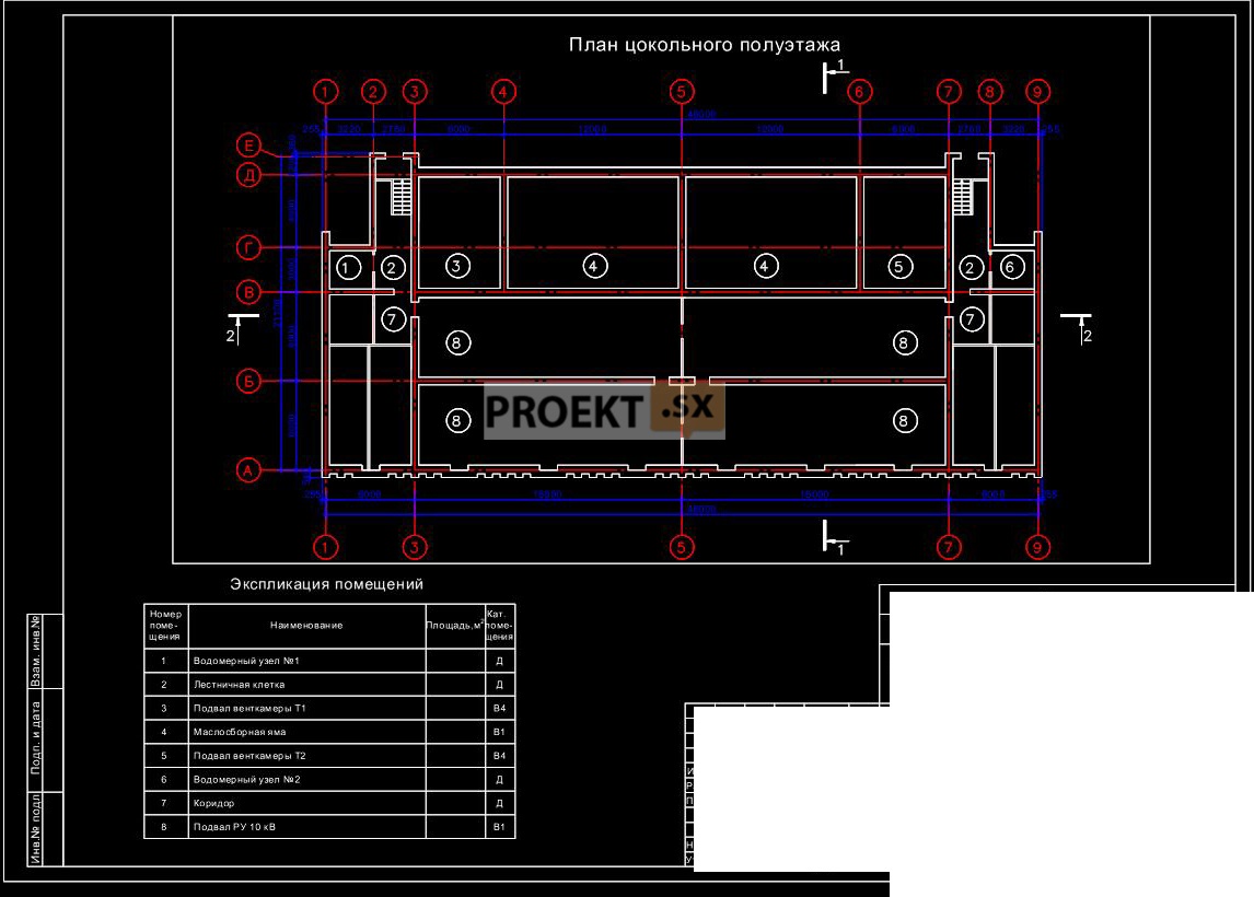
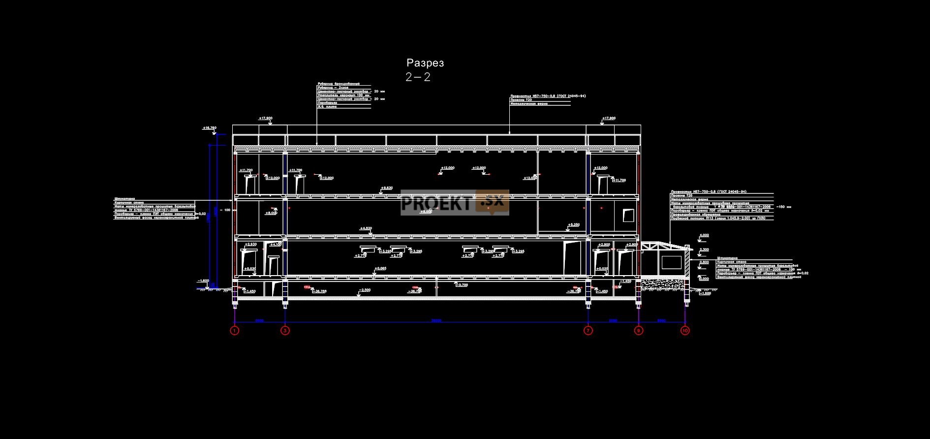
Structural and space-planning solutions
The technical inspection of the building of the closed part of the substation has been completed. The existing administrative and engineering building was built in the 70s - 80s of the 20th century with an incomplete frame. External walls - from red clay brick M100 thick 510-640 mm, working condition. Internal walls - from red clay and silicate bricks 380-510 mm thick, working condition. Basement walls - from red clay bricks M100 thick 610-640 mm. The columns are made of red clay bricks and are in working condition. Intermediate supports for reinforced concrete girders - steel racks of two twin channels, working condition. Above basement and interfloor ceilings - from slabs according to the II24-2, PK-01-111 series. Foundations - reinforced concrete, working condition. The bearing capacity of walls, ceilings, foundations is sufficient to withstand the design loads, the structures do not require reinforcement. The design documentation provides for: dismantling of the existing roof insulation; jointing and chasing cracks in brick walls; installation of a new corrugated board covering on the girders supported by steel trusses made of square tubes of a closed profile. Additional settlement of the building after the reconstruction is not expected. The foundations for the outdoor switchgear portals are designed to be buried up to 3,0 m. The foundations are columnar, prefabricated reinforced concrete according to series 3.407-115. R=2,65 kg/cm2, average pressure under the base of the foundation is 0,82 kg/cm2. The foundations for the DGK installation and other equipment are designed as prefabricated and monolithic reinforced concrete. Concrete B15, W6, F100. Waterproofing - coating. The metal structures of the portal are made of steel C245 in accordance with the series 3.407.9-149.3. The checkpoint building was designed according to the cross-wall structural scheme. External walls - load-bearing brick made of silicate brick M100 on the CPR M25 with a thickness of 510 mm. The insulation is made with mineral wool boards with a ventilated facade. External walls of the basement - brick 510 mm thick, made of ceramic solid brick M100 on CPR M25; internal - 510 mm thick. Overlappings - from prefabricated reinforced concrete multi-hollow slabs with a thickness of 220 mm according to GOST 9561-91. Covering - corrugated board on the girders, based on steel trusses from square pipes of a closed profile. Supporting trusses on the outer walls and a steel purlin from a twin channel No. 36 according to GOST 8240-97, steel C245. The spatial rigidity and stability of the building is ensured by the joint work of the longitudinal and transverse load-bearing walls, and the hard disks of the floor and cover. The rigidity of the floor disk is provided by prefabricated reinforced concrete slabs anchored in the walls, the rigidity of the floor disk is provided by corrugated board. The calculation of load-bearing structures is performed analytically. Stairs - monolithic reinforced concrete. Foundations - in the form of a monolithic reinforced concrete slab 600 mm thick. Concrete B15, W6, F100. The average pressure on the base is 0,38 kg/cm2. A 100 mm thick concrete preparation is provided under the foundation. Sand bedding with layer-by-layer compaction up to Ku = 0,95 is provided for concrete preparation. The connection to the existing building is made with a gap of 300 mm. The relative elevation of 0.000 corresponds to the absolute elevation of +4,500 m. In accordance with the report on engineering and geological surveys the base of the foundation is silty gray water-saturated sands with R=1,5 kg/cm2. Maximum groundwater level - at depth 0,4 ... 0,6 m. Groundwater is slightly aggressive to concrete W4 in terms of HCO3, pH and CO2. In order to protect the concrete of underground structures, the concrete grade for water resistance is W6, the concrete surface is protected by the penetron composition and one layer of waterproofing is applied. The expected average draft of the checkpoint building is 0,82 cm. The expected draft of the adjoining reconstructed hull does not exceed the allowable values. The project indicates the need to organize observations of the existing building adjacent to the checkpoint.
Engineering equipment, utility networks, engineering activities
The existing heating and ventilation systems during the technical re-equipment and reconstruction of the 220 kV substation, due to the unsatisfactory condition of the equipment, are dismantled. Instead of the existing ones, new modern heating and ventilation systems with greater power and productivity have been designed. The heat carrier for substation heating is electricity. Heating is provided by electric heaters with thermostats. The accumulator room is provided with air heating combined with general ventilation, a backup supply unit is provided. The air exchange of the transformer chamber rooms, the reactor rooms is designed to assimilate heat surpluses, to ensure a temperature difference between the supply and exhaust air of 15˚С (and, accordingly, 20˚С). Three supply and exhaust axial fans were designed for ventilation of each transformer chamber. The reactor rooms are provided with independent supply (direct-flow with outdoor air heating up to +5˚С) and exhaust units. Fans are located in separate ventilation chambers. Supply and exhaust ventilation with supply air recuperation is designed to house the DC switchboard, auxiliary switchboard, control panel and automation. In the accumulator room - independent supply and exhaust ventilation. Extraction is carried out by an explosion-proof fan interlocked with process equipment and a deflector from the upper zone of the room. Smoke removal after a fire from gas fire extinguishing sites is carried out by general ventilation in transformer chambers and through ventilation shafts with roof fans - from indoor switchgear rooms. To remove smoke in the initial stage of a fire, smoke exhaust ventilation from the corridor is designed, which is carried out through smoke dampers located in the ventilation shafts under the ceiling. To assimilate heat surpluses during the warm period, air conditioning is provided in the premises of the 3rd floor with split-type air conditioners. Power supply of electrical receivers for auxiliary needs of the 220 kV substation is provided from AC and DC systems for special purposes. The estimated power of 0,4 kV AC power consumers is 229,7 kVA, all power consumers belong to the first category in terms of reliability and in normal mode are powered from the 220/10/0,4 kV network of one of the two main transformers, in the post-emergency mode - from the same network of mutually independent main transformer located in other fire compartments. In normal mode, general substation electrical receivers are distributed between two TSN connected according to the implicit reserve scheme; in the post-emergency mode, the entire load is connected to one of the TSN with a capacity of 400 kVA. DC power receivers are also connected to two SCPTs according to the implicit reserve scheme and are provided with a mutual redundancy device in the post-emergency mode, as well as power supply from batteries for the standard operating time of the corresponding power receivers. The water supply is designed according to the current contract from the public water supply Ø500 mm with a connection point along the street through two Ø100 mm inlets with the installation of a dividing valve on the Ø500 mm network. Guaranteed pressure in the network 28 m.w.st. the required pressure is provided by the utility system. The estimated volume of domestic and industrial wastewater is 0,128 m3/day, the estimated flow rate of rainwater from the site is maintained as it is. The required heat consumption is provided from power sources - TSN transformers, at a voltage of 0,4 kV. Communication systems, information transmission, signaling are designed in accordance with the standards (guidelines for the choice of information volumes) and provide information exchange between substation systems, taking into account the existing FOCL channels over 220 kV overhead lines. The volume of reconstructed main structures of the substation includes: open switchgear 220 kV; a building containing a closed installation of 220/10/10 kV transformers and a 10 kV switchgear; information transmission equipment. Technological solutions provide for the layout of the substation, in which all equipment, protection and control systems of a closed substation, except for a switchgear with a higher voltage of 220 kV, are located in one building. Enclosing structures of the building provide all types of safety - electrical, fire, environmental, social and others. The closed installation of electrical equipment, transformers and other equipment localizes magnetostrictive and fan noise of transformers within the building, as well as possible oil leakage. Electromagnetic emissions at a voltage of 220 and 10 kV do not exceed the standards, both outside the building and inside it. The main scheme of the substation on the side of 220 kV was adopted as standard No. 220-7 "quadrangular". Each connection is provided through two protective switching devices, a sectional jumper on the 10 kV side with two switches, which increases reliability and allows each transformer to be considered as an independent power source that provides power consumers of the first category in terms of reliability. The number of 10 kV switchgear sections is 8. Current-limiting reactors are connected between the 10 kV transformer terminals and 10 kV switchgear sections to maintain the existing TKZ value in the existing 10 kV network. Each transformer has two 10kV step-down voltage windings. The operation of the substation is provided without the constant presence of maintenance personnel. Power transmission lines connecting the designed substation to the existing 220 kV network are overhead, the existing end towers remain, the total number of 220 kV overhead lines is two. Control, protection and signaling systems are made on a microprocessor electronic base in digital format, the main elements are duplicated. The control of the substation is provided by means of automated process control systems with full automation from control rooms and workstations in the substation control room.