Did not you find what you were looking for? Ask us! We have archives of 140 TB. We have all modern reuse projects and renovation projects for Soviet standard buildings. Write to us: info@proekt.sx
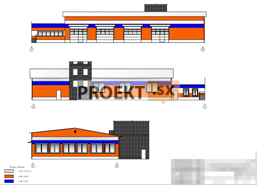
Standard project 416-6-8


Technical and economic, other indicators:
The building has a complex configuration in plan, measuring 11,37 x 28,37 m.
The height of the building is 10 m.
External walls - reinforced concrete panels, brick.
Internal walls - reinforced concrete panels, brick.
Covering - prefabricated reinforced concrete multi-hollow, ribbed slabs.
The roof is flat.
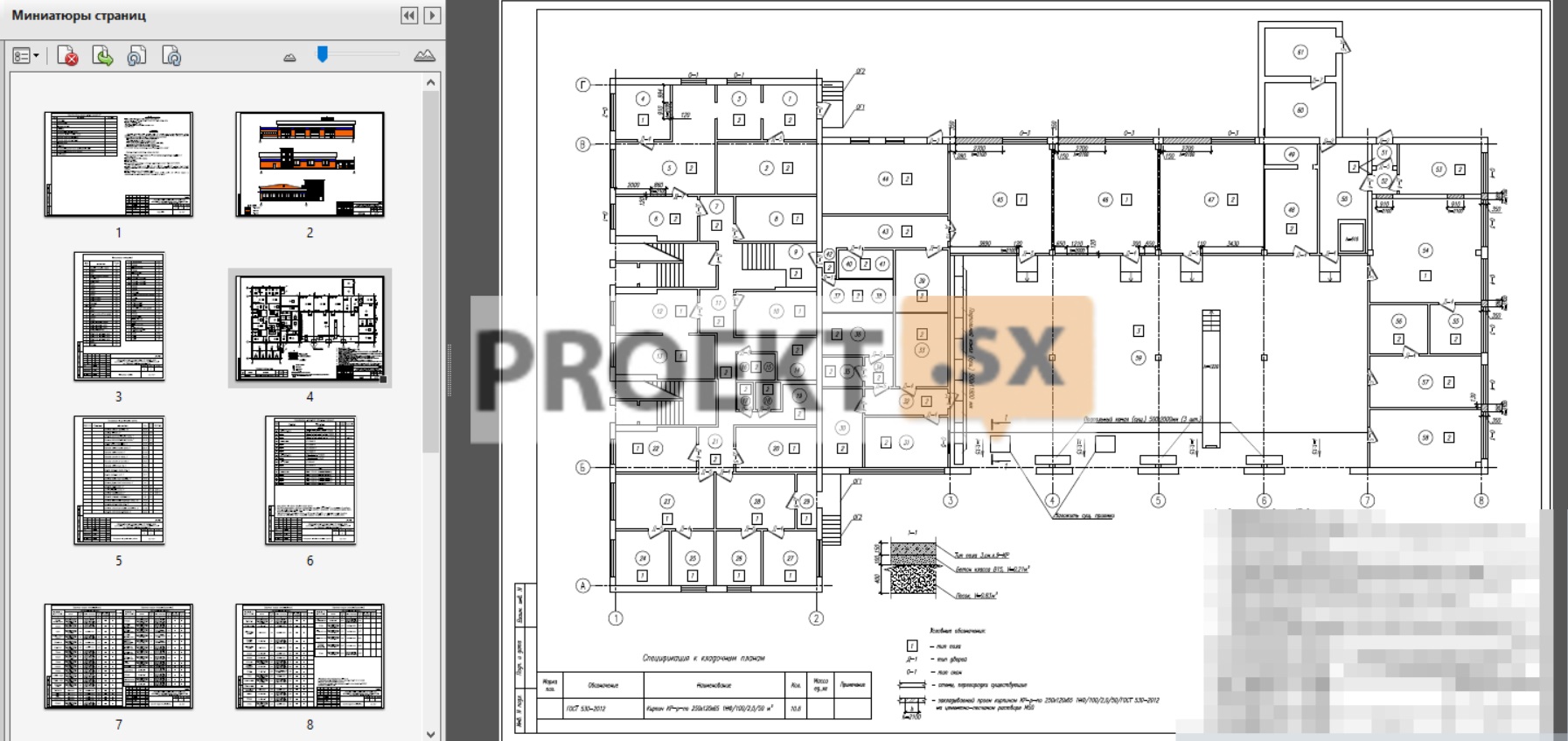
Structural and space-planning solutions.
Capital repairs include the following types of work:
- dismantling of the existing roofing from 2 layers of roofing material of the administrative building = 313,12 m², letter No. 1 = 131,75 m²;
- installation of a new roofing;
- finishing facilities;
- replacement of windows and doors;
- facade cladding with metal siding with insulation with Venty Butts ROCKWOOL mineral wool boards, 100 mm thick, S = 352,07 m²;
- cladding of doorways (S = 3,78 m²), gates (S = 51,8 m²), windows (S = 58,2 m²) in the outer walls with a slope strip made of galvanized steel with a polymer coating, with installation of platbands made of galvanized steel with polymer coating.
- repair of a concrete blind area 70% wide-1m (S = 56 m²);
- repair of pavements of asphalt concrete passage (pitting 30% (S = 133 m²), fine-grained asphalt concrete pavement - grade II, type B, 50 mm thick S = 444 m²
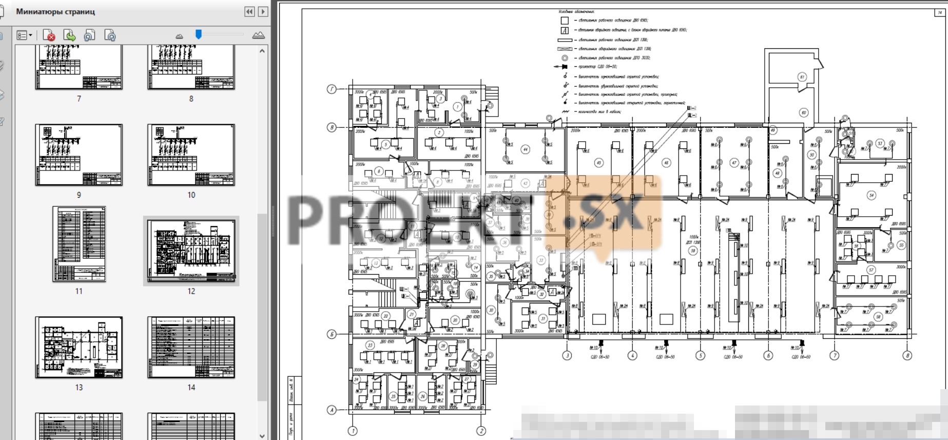
Power supply.
ASU power supply source - existing. The power supply of the ASU is provided by two supply cable lines, from the busbar section RU-0,4kV. For the distribution of electricity, switchboards of the ShchRv type with automatic switches are installed. Accounting for electricity consumption is carried out by electric meters in the introductory panel of the ASU. In order to save energy, the project provides for the following measures:
- the use of energy-efficient lighting devices with LED emitters;
- the use of electrical consumers with a high power factor;
- uneven distribution of a single-phase load over the phases of three-phase lines does not exceed 15%;
- use of multi-tariff energy metering devices;
- the maximum value of the voltage drop between the power source and any load point relative to the value of the rated voltage of the installation in accordance with GOST R 50571.15-2011
- does not exceed 3% for lighting and 5% for other receivers.
The ground loop is existing. Each electrical cabinet has a zero working bus N, isolated from the metal case, and a zero protective PE connected to the case. The main protection against direct contact with live parts of the equipment is provided by the main insulation of live parts and the use of protective sheaths for electrical equipment. As zero protective conductors, the third (in a single-phase network) and fifth (in a three-phase network) cable cores are provided, having a yellow-green insulation color. The main potential equalization (existing) includes: a grounding device consisting of a ground electrode and grounding conductors; the main ground bus GZSH, to which the protective conductors of the electrical installation, PEN conductors of external supply lines and the main conductors of the potential equalization system, laid from outside conductive parts of the building, must be connected; building steel pipes. Additional potential equalization is performed by interconnecting all simultaneously accessible to touch open conductive parts of stationary electrical equipment and third-party conductive parts, including touchable metal parts of the building structures of the building (including metal frames of doors, hatches), as well as zero protective conductors, including protective conductors of socket outlets. Metal air ducts are connected to the PE busbars of the ventilation unit control cabinets. The continuity of the metal structures of the air ducts is ensured with the help of jumpers made with the wire PUVNG(A)-LS-1*6mm². Additional equalization of metal boxes for laying cables was carried out with the wire PUVNG(A)-LS-1*6mm², connecting it from different ends of the route. Lightning protection existing. Information about the type, class of wires and lighting fittings. The design documentation provides for distribution and group networks of the building. The supply line was not developed in this project. Distribution lines are designed with VVGng(A)FRLS, VVGng(A)LS-0.66kV cables. Cable laying is provided in a PVC pipe, in a strobe. Distribution and group cables are laid: vertical sections - in a PVC pipe, in a strobe. horizontal sections - in a PVC pipe behind a false ceiling, in a strobe. The places where wires and cables pass through walls, interfloor ceilings or exit to the outside are carried out in openings. In order to prevent the penetration and accumulation of water and the spread of fire in places of passage through walls, ceilings or exits to the outside, the gaps between wires, cables and the opening are sealed with an easily removable mass of fireproof material. The seal must allow replacement, additional laying of new wires and cables and ensure the fire resistance of the opening is not less than the fire resistance of the wall (ceiling). The conductors of the potential equalization system are made with PUVNG(A)-LS wire of green-yellow color and are laid together with cables of group lines in boxes along prefabricated cable structures and walls openly. Lighting devices with LED emitters are used as a light source. Light indicators are equipped with built-in batteries. The use of stationary lighting fixtures with a voltage of 220V and portable repair lighting fixtures with a voltage of 36V is envisaged. All electrical equipment (lamps, switches, sockets and other devices) has a degree of protection of the shell, which corresponds to environmental conditions. All lamps dignity. nodes have class 2 protection against electric shock.
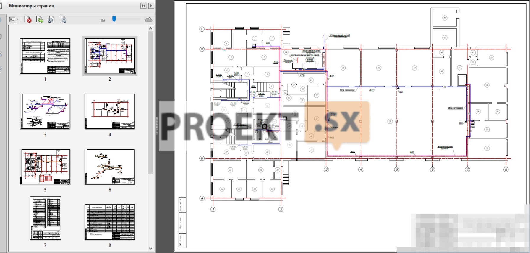
Water supply and sewerage.
The working drawings were made on the basis of the task for the overhaul of the task, construction drawings and in accordance with the current norms and rules for building design SNIP 2.04.01-85. The building provides for the replacement of water supply systems, fire water supply and sewerage. The source of water supply is the existing water supply network. There is 1 water supply. A water metering unit was designed to account for water. The distribution of the cold water supply system is designed from polypropylene PPRC РN 16. The source of hot water supply is from a single-circuit gas boiler. The cold water distribution system is designed from PPRC PN 20 polypropylene. The laying of internal sewer networks should be provided from the SINIKON Standart PP.
Heating.
The working drawings were made on the basis of the task for the overhaul of the task, construction drawings and in accordance with the current norms and rules for building design SNiP 41-01-2003, SaNPiN 2.4.2660.10. The calculated outdoor air temperatures are taken according to SNiP 41-01-2003 and are equal to -31 °С in winter for heating design. The source of heat supply is the existing boiler house. Estimated parameters of the coolant 95-70°C. The heating system is two-pipe, the distribution of the supply and return lines. The building provides for the replacement of main pipes, risers of the heating system, heating fittings and gas boilers. Aluminum radiators Rovall 500/100, H=500mm, (f=197 watts) are used as heating devices. Reinforced PN20 pipes are used for the heating system. Pipelines are laid in underground channels in thermal insulation of the "Korund" type for pipes. To regulate heat transfer, manual thermostatic valves from Danfoss are installed on the connections to the heating devices, manual balancing valves ASV-C ("Danfoss") are provided on the risers. Air removal is carried out through Mayevsky taps installed in the upper plugs of each heater and automatic air vents of the WIND type in the upper parts of the line. The consumption of heat is accounted for in the boiler room. Pipelines at the intersection of ceilings, internal walls and partitions should be laid in sleeves made of non-combustible materials. At the lower points of the system, taps are installed to drain the coolant. Do not allow rigid fastening of heating devices to enclosing structures. Manufacturing, installation and testing of the heating system is carried out in accordance with SNiP 3.05.01-85.
APS
List of protected premises
In accordance with SP 5.13130 2009, the facility is subject to automatic alarm installation (AUPS).
The building has the following rooms:
a) warehouses, corridors, offices, service premises. (The premises are equipped with smoke detectors in accordance with SP 5.13130 2009 tab. M1).
b) bathrooms, showers. (Premises with wet technological processes are not equipped with fire detectors).
c) Garage. (The premises are equipped with heat detectors in accordance with SP 5.13130 2009 tab. M1).
Main technical solutions adopted in the project
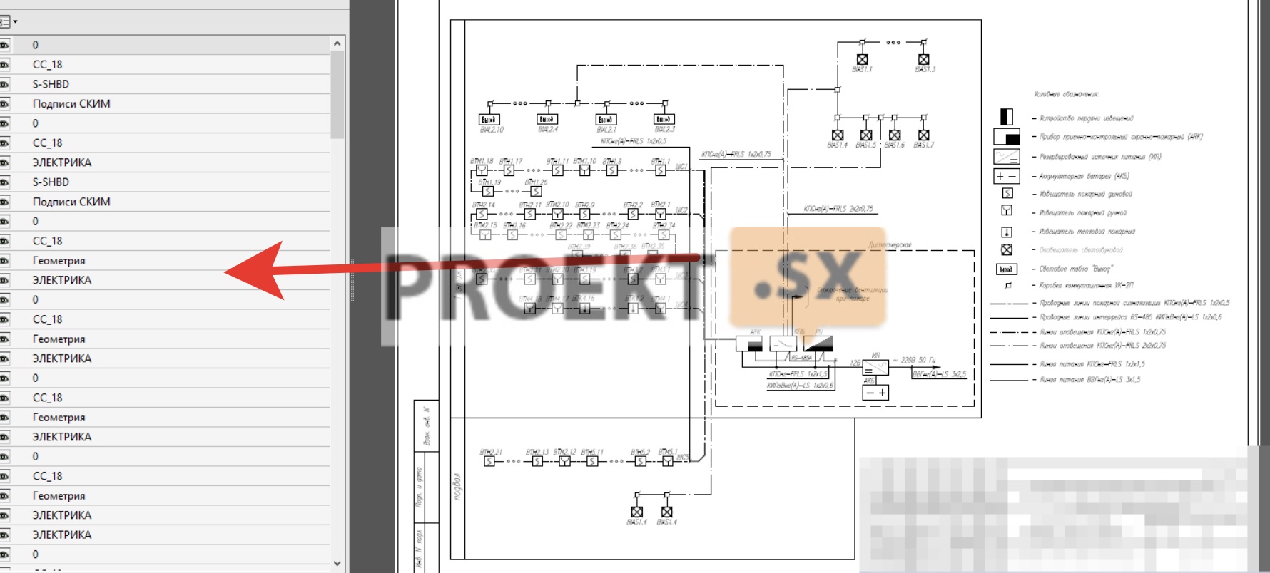
The construction of the OPS is carried out on the basis of technical means, which include:
- fire and security control panel "Signal-20M" 1 pc.
- fire smoke detector IP 212-141 108 pcs.
- manual fire detector IPR513-10 14 pcs.
- thermal fire detector IP 103-5/1-A3 (NC) 15 pcs.
- light and sound annunciator "Mayak-12KP" 9 pcs.
- indicator board "Exit" Lightning-12 10 pcs.
- control panel "S2000-M" 1 pc.
- control and launch block "S2000-KPB" 1 pc.
The projected receiving and control device is installed in the control room. The technical solution provides for the use of the Russian device of the fire and security alarm and control system "Signal-20M", which provides duplication of the alarm signal, both through the GTS line and through the GSM channel. The warning system is designed to alert people in the event of a fire on command from an automatic fire alarm system. The choice of the method of warning people about a fire was carried out according to SP 3.13130.2009. The object is equipped with a fire warning system and evacuation control of people of the II type. The specified type requires the inclusion of light and sound annunciators and light displays "Exit" in the system. Light and sound annunciators receive a command impulse from the S2000-KPB outputs. Light annunciators receive a command impulse from the "Lamp" outputs of "S2000-KPB". There is no provision for splitting into warning zones. All premises are subject to automatic fire alarm protection, except for premises with wet processes and stairwells, vestibules. IP 212-141 smoke detectors were selected to detect a fire at an early stage of a fire. To issue a signal "FIRE" in case of visual detection of a fire by duty or maintenance personnel, install manual fire detectors IPR513-10. Installation is provided along escape routes, on walls with free access to the detector. The installation height from the level of the finished floor to the center of the manual call point is 1,5 m. The distance between the manual call points does not exceed 50 m (p. 13.13.2, SP 5.13130 2009). Connection of fire alarm loops with smoke and manual fire detectors to "Signal-20M" should be carried out by KPSng(A)-FRLS 1x2x0,5. Connect sound and light alarms with cables KPSng(A)-FRLS 2x2x0,75 and KPSng(A)-FRLS 1x2x0,75, respectively. Laying of loops to produce in el. tech. PVC boxes 25x16mm and 20x10mm. Lay fire alarm loops in protected premises and along routes separately from all power, lighting cables and wires. With parallel open laying, the distance between the wires and cables of fire alarm loops and connecting lines with power and lighting devices must be at least 0,5 m. The number of fire detectors in the loop does not exceed the allowable current consumption specified in the technical passport for Signal-20M . Fire detectors are powered by loops. Connection and location of fire detectors and fire alarm loops are shown in the diagrams. The placement and installation of fire detectors must be carried out in accordance with this project, the requirements of the standards and the instructions for the equipment. Installation of technical means should be carried out in accordance with the project. All deviations from the design solution must be agreed with the design organization and supervisory authorities in writing, with a reasonable calculation confirming the reliability of the fire protection of the building for these deviations from the project. The installation organization must familiarize themselves with the project and examine the equipment used before work. The equipment is allowed for installation and installation after the input control with the drawing up of an act in the prescribed form. Warning and evacuation management system in case of fire The warning system is designed to alert people in the event of a fire on command from an automatic fire alarm system. The choice of the method of warning people about a fire was carried out according to SP 3.13130 2009. tab. 2. The facility is equipped with a type 2 fire warning and evacuation management system. The specified type requires the inclusion of light and sound annunciators and light displays "Exit" in the system. As equipment for the warning system and management of people's evacuation in case of fire, the project provides for: a control and launch unit "S2000-KPB"; combined light and sound announcer "Mayak-12-KP"; light board "Exit" Lightning-12. Principle of operation of the system: In standby mode, reverse polarity current flows in the loops of the S2000-KPB device, which controls the integrity of the alert loops. When an alarm signal is received from the fire alarm equipment to the warning and evacuation control system in case of fire, a current of direct polarity is supplied to the loops of the S2000-KPB device and the following are switched on: “Exit” light displays and light and sound annunciators. SOUE is controlled by APS.