Did not you find what you were looking for? Ask us! We have archives of 140 TB. We have all modern reuse projects and renovation projects for Soviet standard buildings. Write to us: info@proekt.sx
Boiler house project 5,5 MW


Design, working documentation, including estimates, and the results of engineering surveys for the construction of a boiler house
Technical and economic characteristics of the capital construction object
Length of heating networks, running meters: 1014,2
Plot area within the boundaries of the land allotment, m2: 320,0
Building area, m²: 100,44
Total building area, m²: 96,0
Construction volume of the building, m3: 366,6
Number of floors, floor: 1
Productivity, MW: 5,5
Estimated cost at the 2001 base price level (without VAT)
Total, thousand rubles: 16938,03
Construction and installation works, thousand rubles: 5662,87
Equipment, thousand rubles: 9795,76
Other expenses, thousand rubles: 1479,40
including:
PIR, thousand rubles: 867,55
refundable amounts, thousand rubles: 25,20
Estimated cost at the current price level as of October 2010 (including VAT)
Total, thousand rubles: 68529,50
Construction and installation works, thousand rubles: 28339,32
Equipment, thousand rubles: 33521,11
Other expenses, thousand rubles: 6669,07
including:
PIR, thousand rubles: 3123,87
VAT, thousand rubles: 10450,38
refundable amounts, thousand rubles: 126,09
Architectural and space-planning solutions
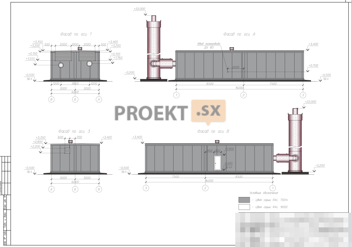
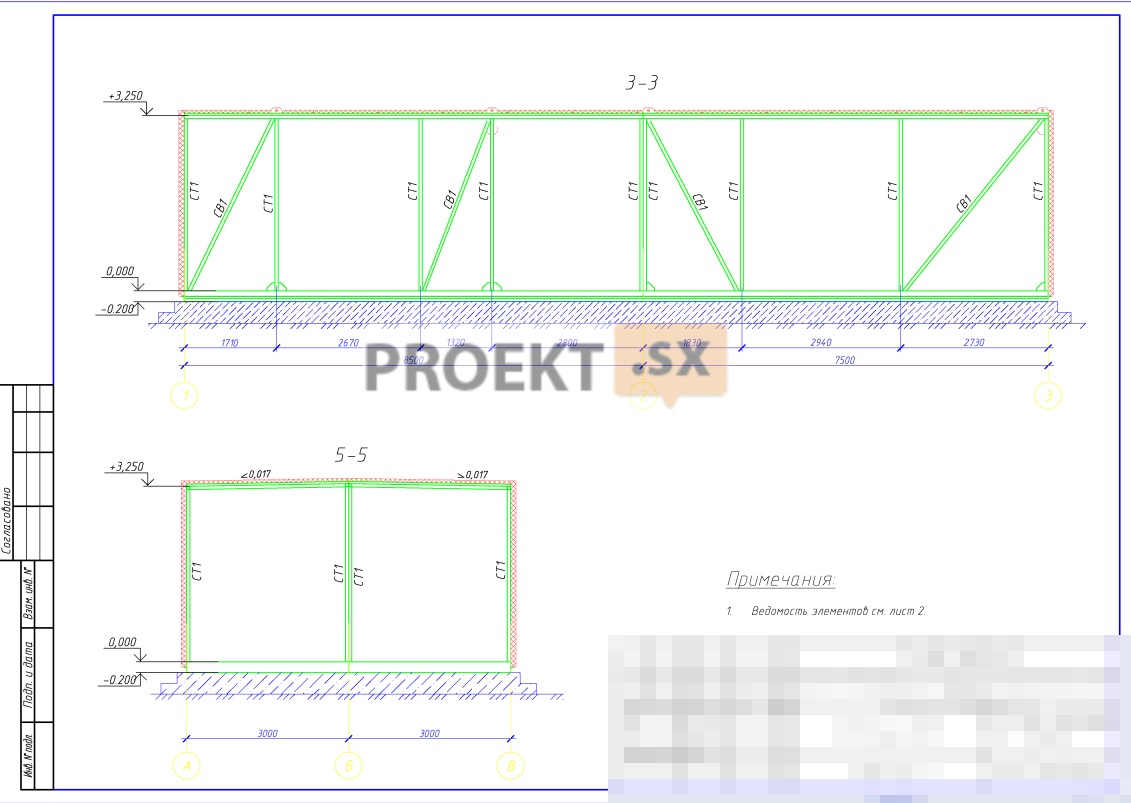
The boiler room is designed without a basement and an attic, with dimensions in the axes of 6,0 x 16,0 m, a height of 3,65 m from the level of the blind area. External walls - three-layer panels with mineral wool insulation. The panels are attached to a steel frame. Easily foldable structure - roof panels with an area of 100,4 sq.m. A chimney was designed - a column-type steel structure, inside of which two heat-insulated gas outlet shafts with a diameter of 600 mm are fixed. The diameter of the supporting column is 1600 mm, the height from the ground level is 21,07 m. The height of the gas exhaust shafts from the ground level is 22,0 m.
Structural and space-planning solutions
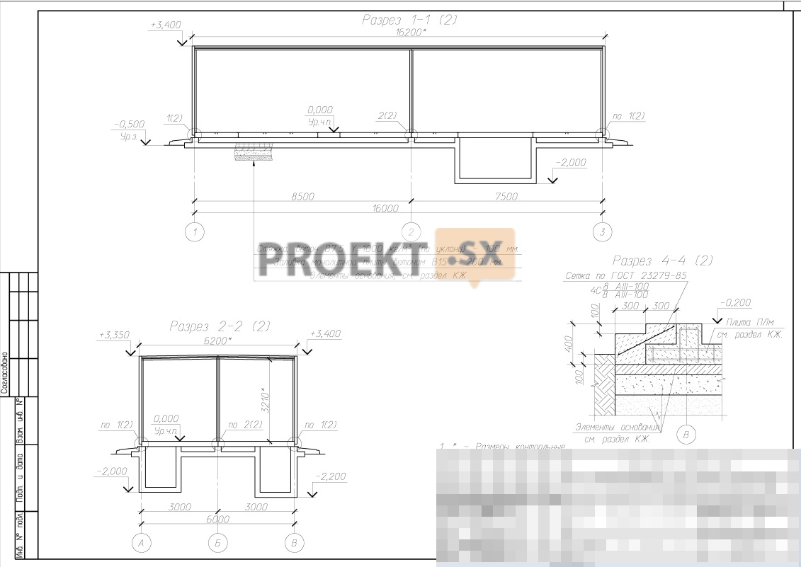
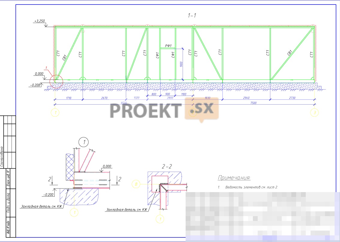
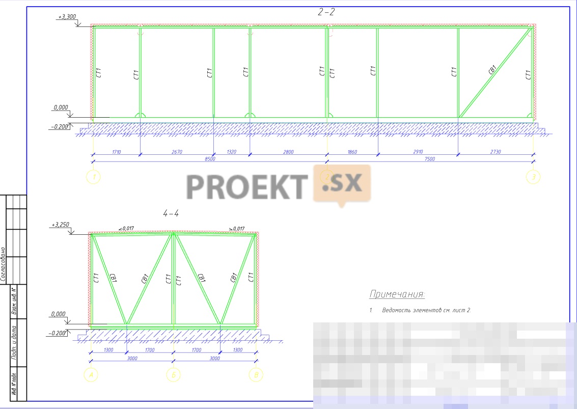
Building responsibility level – II (normal). The design of the boiler house is a factory-made mobile container-type building "AKM Signal 5500". The constructive scheme of the boiler house is frame-bonded. Frame - steel, steel C245. The outer walls are made of sandwich panels with a thickness of 100 mm vertically mounted. Columns - from bent-welded profiles of closed section. The support frame is made of rolled channel. The covering is made of sandwich panels with a thickness of 100 mm on a system of cross beams from rolled channels. The spatial rigidity and stability of buildings is provided by a frame frame and the installation of vertical and horizontal ties. The pits in the boiler room with a depth of 1,6 - 1,8 m are designed from monolithic reinforced concrete, the thickness of the walls and bottom is 200 mm. For the relative mark of 0.000, the absolute mark of 19.000 is taken. The foundation for the boiler house building is a monolithic reinforced concrete ribbed slab made of concrete class B15, F75, W4, 200 mm thick for concrete preparation made of concrete B7,5, 100 mm thick. The base of the slab is a preparation of crushed stone 200 mm thick for sand preparation 1,05 m thick, with a design resistance of 1,58 kg / cm2. The maximum pressure on the base is 0,22 kg/cm2. The foundation for the chimney is taken columnar from monolithic reinforced concrete of class B25, F75, W4, with an anchor basket, the laying depth is below the freezing depth. The foundation of the pipe is designed in accordance with the given loads (N= 12,0 tf, M=17,8 tf.m, Q=1.6 tf). The design of the chimney was not considered. The calculation of the foundations was carried out according to the "Foundation" program. The expected draft does not exceed 1,0 cm, list 0,00068. Concrete preparation - from concrete class B7,5 with a thickness of 100mm. In accordance with the report on engineering and geological surveys, the base of the foundation is EGE-3 soil, light silty loam, semi-solid, brown in color with φ=22º, e=0,683, E=120kg/cm2. Waterproofing of pits is coated. The normative depth of freezing of sandy loam is 1,45 m. To prevent freezing of soils under the base of the foundation, a layer of Penoplex 35 insulation 50 mm thick is provided under the blind area.
Engineering equipment, utility networks, engineering activities
Twelve residential buildings are subject to provision of thermal energy for heating and hot water supply systems with a total heat load with GVSMAX / GVSSR - 4,329 / 5,207 MW (3,720 / 4,478 Gcal / h), including for heating - 3,58 MW (3,079 Gcal / h); for GVSSR - 0,54 MW (0,464 Gcal/h); GVSMAX - 1,418 MW (1,22 Gcal/h). The heat supply system is four-pipe. Heat carrier for heating systems - water Т1/Т2 = 95/700; for DHW systems - T3 / T4 \u65d 500 / XNUMXС. In accordance with the location of the connected residential buildings relative to the designed boiler house, two underground outlets of heat networks in different directions are provided from the latter. First issue: 2D219x6,0; GVS-D108x4,0 and D89x4.0. Second issue: 2D159x4,5; GVS-D89x4,0 and D76x3,0. In both directions, the laying of heat networks from the boiler house to the ITP of buildings is combined - channelless, partly in impassable reinforced concrete. canals, and in transit through cellars inside buildings. The laying of heat networks in channels is accepted at the corners of the route, when crossing playgrounds and when laying at a distance from the foundations of buildings less than those required by SNiP 41-02-2003. At the intersection of roads and utilities, the laying of heating networks is provided in steel cases; at the intersection of intra-quarter passages - using unloading railroads. b. slabs. The pipe diameters are taken in accordance with the hydraulic calculation. The following pipes are accepted as pipes: for underground laying of network water pipelines - factory-made steel pipes in polyurethane foam insulation in a polyethylene sheath with ODK for the state of moisture content of thermal insulation; polymer pipes in thermal insulation made of polyethylene foam in a corrugated plastic casing (DN 140 mm and less); for laying pipelines of hot water systems - prefabricated stainless steel pipes in polyurethane foam insulation in a polyethylene sheath with ODK and polymer pipes in thermal insulation made of polyethylene foam in a corrugated plastic casing. Electric-welded steel pipes are used for laying network water pipelines inside buildings and in chambers; for hot water systems - PRR polypropylene pipes in thermal insulation made of mineral wool. Thermal insulation of all transit pipelines and chambers is made of mineral wool mats cached with aluminum foil. Drainage from the systems is provided through waste wells into the sewer. Boiler room. The source of heat supply is a separately standing automated heating boiler house being designed. The boiler room provides for installation of two hot water automated gas boilers Termotekhnik TT 100 with a capacity of 3000 kW and 2500 kW. manufactured by Entroros LLC. The installed capacity of the boiler house is 5500 kW. Three-circuit boiler room. The first circuit is a boiler room with a coolant of 110-700C; the second - network heating systems with a coolant of 95-700C and the third - hot water supply systems with a coolant of 650C. Connection of heating systems to heating networks - through two plate heat exchangers M10-MFM (3765 kW) at 100% capacity from Alfa-Laval with automatic control of the temperature of the coolant according to the temperature schedule. The hot water supply system is closed, circulating through two M6-FG plate heat exchangers (795 kW) at 50% capacity from Alfa-Laval with automatic maintenance of the heat carrier temperature. For the circulation of the boiler circuit, pumps IPL 100/175 are provided; for network water of the second circuit - network pumps IPL 100/165; for hot water supply - the third circuit - MHI 403 circulation pumps. Boiler and network circuits are fed automatically from the domestic drinking water supply after chemical treatment using the TEKNA APG 603 dosing unit. Accounting for the generated thermal energy of the boiler house is provided by the heat calculator SPT with temperature sensors KTTPR-0,1 and counters PREM. The boilers are equipped with Entromatic 50.01 and 50.02 safety, control and regulation systems. Gas supply to the boiler house is provided in accordance with the Technical Specifications from the designed medium pressure gas pipelines across the territory of the residential complex with a connection point on the facade of the boiler house. The gas pressure at the inlet is 0,2 MPa. The maximum gas flow rate is 642 m3. The following are provided at the gas pipeline inlet: a KTZ-001 thermal shut-off valve, shut-off valves, a FNZ-1 filter, a PNZN-3 solenoid valve and a commercial gas metering unit based on a STG-80-250 gas meter. The boilers are equipped with oilon GP-280 and GKP-280 gas burners equipped with DMV-D multiblocks with solenoid valves and tightness control. On the branches of gas pipelines to the boilers, the following are provided for installation: shut-off fittings, a filter, a gas pressure regulator with a built-in shut-off valve, a PSK and a compensator. The operation of boilers and burners is controlled by the Entromatic 50.01 and 50.02 control systems developed as part of the project documentation. As part of the project documentation, design solutions have been developed for the two-threshold protection of the boiler room from CH4 and CO gas contamination with an alarm at the first gas contamination threshold and shutting off the gas supply to the boiler room at the second threshold. Fire protection is provided taking into account the automatic shutdown of the gas supply at a temperature of 1000C and when a fire alarm is triggered. As part of the project documentation, sections with design solutions for automation and dispatching have been developed; on an automatic powder fire extinguishing system and a burglar alarm. Water supply (cold water) for consumers of the facility, in accordance with the specifications, is provided from the public water supply network through 2 looped inputs D = 110 mm. Guaranteed head at the connection point 25 m w.c. Art. The estimated consumption of cold water for production needs is 149,9 m3/day, including according to specifications. For the boiler house, the installation of water metering units according to TsIRV 02A.00.00.00 l.l. is provided. 268,269 with counter D=65mm. External fire extinguishing is provided from a fire hydrant D = 125 mm, installed on intra-quarter networks in well No. 3. Water consumption for external fire extinguishing - 10 l / s. Stainless steel pipes according to GOST9941-81 were selected for the device of the water supply system. Water treatment of the boiler house - ASDR "TEKNA APG603" based on a complexone with an automatic dosing unit. For the preparation of hot water in the amount of 142,9 m3 / day. high-speed heaters are provided. Required pressure - 35 m of water. To increase the pressure of the source water, a Wilo MHIE 1602-2g pump is provided. Hot water temperature (Тз) – 65°С. Removal of domestic wastewater in the amount of 10,74 m³/day. and rainwater with a flow rate of 1,92 l / s. provided for the release of D \u110d 265 mm into the well No. XNUMX of the intra-yard combined sewerage. Wastewater treatment is not provided. Power source - Substation 220/10 kV "Slavyanka". Power supply, in accordance with the specifications, is provided from the new BKTP (R) No. 4 and 2 BKTP No. 1 of quarter 1 microdistrict via two cable lines. The number of cables in the cable line is 1. Cable APvBbShp 4x50 is accepted for laying. Connection point - cable lugs of two cable lines 0,4 kV from 2BKTP No. 1 of quarter 1 in the input switchgear of the boiler room. The design load for the second category in terms of power supply reliability is 64,6 kVA. Category 1 consumers in terms of power supply reliability include emergency lighting and fire-fighting equipment. To provide consumers with the first category of reliability, an uninterruptible power supply IDP-1/1-2-220-D is provided. For guaranteed power supply, a diesel generator set is connected. Mains voltage - 380/220v. Power supply to consumers of electricity in the boiler house is provided from two independent sections of the designed switchboard ShchR2. For power supply of each SHR2 section, a separate cable is provided from a separate protection device installed in the ATS. Electricity metering is provided for two power inputs of the boiler room. The installation of two three-phase electricity meters Mercury 230ART-03RN direct connection is provided. For laying power networks, cables of the NYM, VVG brand and wires of the PVS, PVZ brand were selected. Lighting fixtures with incandescent lamps and ARKTIC 2x36 fluorescent lamps were chosen to illuminate the premises. For emergency lighting, luminaires of the VZG type are installed. To ensure electrical safety, a potential equalization system and installation of protective devices are provided. Lightning protection - on the third level of protection. To automate the operation of the boiler plant AKM "Signal 5500", automatic control systems "ENTROMATIC" are provided. For scheduling the operation of the boiler house, information is transmitted to the central control room via a GSM communication channel. The following information is provided for transmission to the control room: emergency signals in the technological part of the boiler room, a signal about the position of the shut-off valve at the inlet to the boiler room, boiler room gas contamination signals, boiler room fire and security alarm signals, boiler room operation parameters. The heat carrier in the heating system of the boiler room is water with a temperature of 105-70°C. Heating of the boiler room is designed to maintain a temperature not lower than +5°C and is solved due to heat transfer from process equipment and pipelines and the use of air-thermal curtains. The devices are provided with the installation of control and shut-off valves. Pipelines to heating devices are laid openly. Pipeline material - steel water and gas pipes GOST 3262-75 and GOST 10705-80. Supply and exhaust ventilation is provided in the boiler room, designed for a single air exchange of general ventilation in the cold season and for the assimilation of excess heat in the warm season, as well as providing the air flow necessary for fuel combustion. Air inflow for general and process ventilation is designed through louvered grilles in the outer enclosures. Air removal - through combustion devices and a deflector installed on the roof of the building. When the maximum allowable air temperature in the boiler room is reached, the axial fan is switched on automatically.