Did not you find what you were looking for? Ask us! We have archives of 140 TB. We have all modern reuse projects and renovation projects for Soviet standard buildings. Write to us: info@proekt.sx
Pumping station project


Project documentation without estimates and results of engineering surveys for the construction of a make-up water pumping station (without gravity conduits of the run-of-river water intake)
Technical and economic characteristics of the capital construction object
Land area, ha: 0,2002
Building area, ha: 0,0183
Makeup Water Pumping Station Building (NSWF)
Area, m2: 144,0
Construction volume, m3: 1343,0
Floors, fl.: 1
Type of pumps EMU K 221-1, pcs.: 4
Productivity, m3/hour: 600
Head, m of water st.: 34
Type of pumps PF1 65/160.132-20-3/2-106, pcs.: 2
Productivity, m/h: 30
Head, m of water st.: 16
KTPN building
Area, m2: 27,-4
Construction volume, m3: 74,0
Floors, fl.: 1
Productivity, kVA: 630
The length of engineering networks, including:
Power supply networks:
CL-6,0 kV, m: 1855,0
CL-6,0 kV, m: 30
CL-0,4 kV, m: 118,0
Water supply networks - 2DN 800, m: 9,0
Water disposal networks - 2DN 400, m: 17,0
Water disposal networks - 2DN 200, m: 28,63
Architectural and space-planning solutions
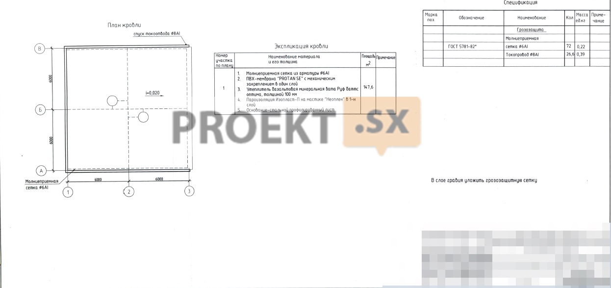
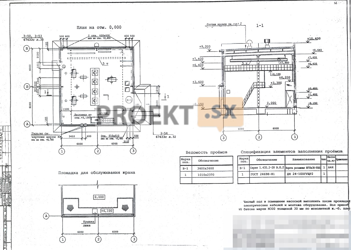
The building of the make-up water pumping station was designed on the industrial site of the thermal power plant, located on the right bank of the river, and is technologically connected with the main building of the power unit. The make-up water pumping station is a one-story building with an elevation of 8,640 m to the bottom of the rafters and a height of 10,550 m to the top of the parapet from the elevation of the adjacent territory. The dimensions of the building in plan and in height are taken from the condition of placing technological equipment and in the axes are 12,0x12,0 m, the mark to the tracks of the suspended crane beam with a lifting capacity of 5,0 tons is 7,900 (floor mark 0,000). The building is heated, with an internal air temperature of at least +5°C. The degree of fire resistance of the building - IV. Category of explosion and fire hazard of the building - D. Class of constructive fire hazard of the building - CO. In addition to the equipment at the 0,000 mark, there is a platform for maintenance and repair of the overhead crane. The facades of the building are painted in a single color scheme, taking into account the requirements. When developing the architectural solution of the building, the principle of sheltering equipment from the side of city highways was adopted. The interior of the pump room was determined from the condition of the layout of the main equipment - its placement in a single hall-type volume, which has natural light through windows in the outer walls. The solution of the interior is determined by the structures of the building ("sandwich" - panels and light steel supporting structures). The solution of the facade is also determined by the use of building structures (basement prefabricated reinforced concrete 3-layer prefabricated wall panels 1,400 m high, 250 mm thick with fireproof insulation from basalt fiber, external walls - "sandwich" - production panels 1,0 m high, with insulation from basalt fiber, 100 mm thick). Windows - single-chamber, doors - metal. Gates - metal oar with a gate, floor coverings - polymer bulk. The roof of the building is single-pitched with an external drain with a slope towards axis 3, made of galvanized profiled sheet with insulation made of basalt mineral wool with a volumetric weight of 125 kg/m50 and a thickness of 800 mm. As a waterproofing carpet, PVC is provided - a membrane of the Sikaplan type with fastening to the wall panels of the parapet. An asphalt pavement XNUMX mm wide is provided around the pump house building, made on compacted gravel soil.
Structural and space-planning solutions
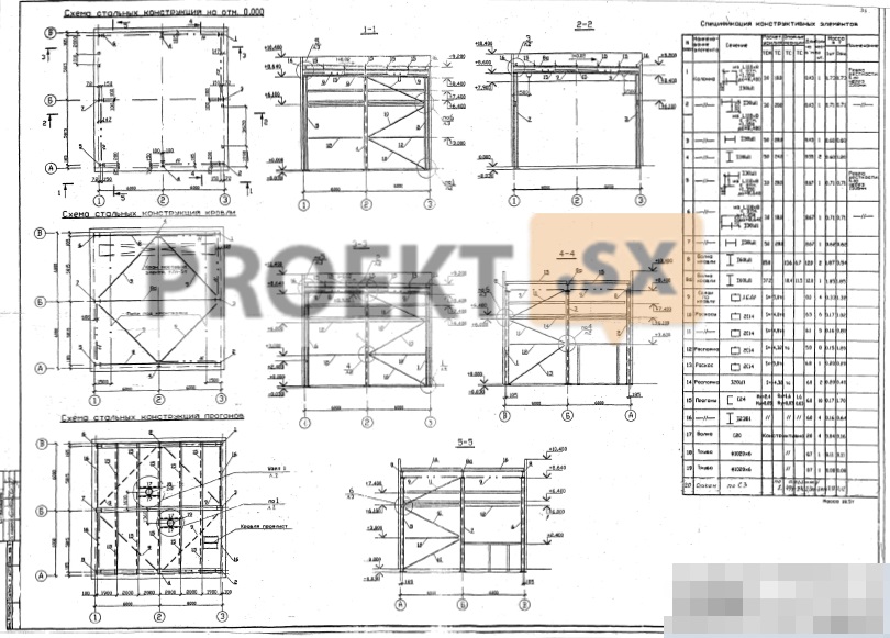
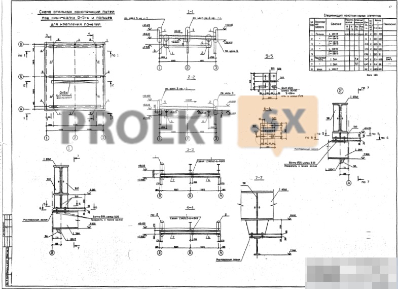
The buildings of the additional water pumping station are designed in a steel tie frame with an underground part made of monolithic reinforced concrete. The main load-bearing structures of the frame are columns and crossbars made of rolled wide-shelf I-beams and channels. Covering - profiled flooring on steel girders from channels. Rigidity and stability of the frame is ensured by the rigid connection of the racks with the foundation, the presence of vertical ties and the hard disk of the coating. The rigidity of the coating disc is provided by horizontal ties. External walls - hinged "sandwich" - panels 100 mm thick. The panels are attached to the frame columns and to the half-timbered elements. Along the perimeter of the outer walls, there is a plinth made of prefabricated reinforced concrete three-layer panels 250 mm thick, 1400 mm high. The buildings are equipped with an overhead crane-beam with a lifting capacity of Q=5 tf. The relative mark of 0,00 corresponds to the absolute mark of 7.40. The underground part of the pumping station building is designed in the form of a round fall well with a diameter of 12 m; the depth of the bottom of the well is 12,15 m from the surface of the earth. The fall well is designed from monolithic reinforced concrete B25; W6; F100, wall thickness - 400 mm, bottom thickness - 600 mm. On the top of the well, a power slab made of monolithic reinforced concrete B25 is provided; W6; F150, on which the columns of the frame of the above-ground part of the building rest. The power plate is adopted in the form of cross beams with a height of 1120 mm, united along the top with a cast thickness of 250 mm. Under the bottom of the well, concrete preparation is provided for a layer of crushed stone. At the base of the slab of the bottom of the well there are light silty loams with gravel pebbles, refractory (EGE 3) with design characteristics: c = 12 kPa; E=13 MPa; e=0,554; cf=14 deg. The project provides for the installation of a KTPN transformer substation from prefabricated reinforced concrete elements manufactured by ZAO Electronmash. The foundations are taken on a natural basis, in the form of a monolithic reinforced concrete slab 300 mm thick made of concrete B25, W6, F100. The relative mark of 0,00 corresponds to the absolute mark of 7.15. Under the foundations, concrete preparation is provided for a gravel-sand cushion 300 mm thick. At the base of the foundation there are loamy layered refractory (EGE 2.1) with design characteristics: c=24 kPa; E=12 MPa; e=0,743; Ф=14 deg. To protect the buried part of the substation from groundwater, bitumen coating of the surfaces of the underground walls is provided. The fencing of the territory is designed in the form of steel lattice sections 2,7 m high of the Pallada-8 type with supporting structures in the form of metal racks; the pitch of the racks is 3,1 m. The foundations for the fences are on a natural base, tape made of monolithic reinforced concrete B25; W6; F150; foundation laying depth - 1,4 m from the ground surface.
Engineering equipment, utility networks, engineering activities
Water supply and sanitation - in accordance with the technical specifications. The design documentation provides for the laying of gravity water conduits within the boundaries of the land plot. Design solutions for the construction of run-of-river conduits with heads outside the boundaries of the land plot will be presented in a separate project. Water supply is provided through two gravity water conduits with a diameter of 820 mm made of steel electric-welded pipes according to GOST 10704-91 (with a very reinforced bitumen-rubber insulation in 3 layers of the outer surface) in steel cases with a diameter of 1020 mm (with epoxy-perchlorovinyl insulation reinforced with glass fabric in 3 outer surface layer). The additional pumping station is an underground part with a diameter of 12 meters (water intake chamber), divided into 2 halves and an above-ground part 12 x 12 m. Each half of the water intake chamber has its own conduit equipped with a butterfly valve. In each half of the underground part, two pumps are installed with a capacity of 600 m34 / h, a head of XNUMX meters of water column (one working, the second reserve). The flow rate of cold water supplied to make up for losses in technological cycles and the circulating system of technical water supply is 1000 mXNUMX/hour. The dividing wall of the underground part provides for the installation of a bypass pipe with a butterfly valve, in the power slab of the underground part there are hatches for descending into the water intake chambers to pumps and butterfly valves. To drain the water intake chambers, one submersible pump with a capacity of 30 m3/hour and a head of 16 meters of water column is installed in each half of the underground part of the pumping station. Drainage is carried out by pumping water into an adjacent chamber. From the pumping station, 2 pressure conduits with a diameter of 426 mm are provided from steel electric-welded pipes in accordance with GOST 10704-91 with a connection point to the existing networks of the enterprise at the border of the land plot. For the possibility of flushing gravity inlet conduits, a collector with a diameter of 300 is provided from steel electric-welded pipes according to GOST 10704-91 mm from pressure pipelines of additional water with a tie-in into gravity conduits in water intake chambers. A combined system of technical and internal fire-fighting water supply was designed for the facility. The required pressure for technological needs is 29,27 meters of water column. The required pressure for internal fire extinguishing of the pumping station is 28,11 meters of water column. Electric welded steel pipes according to GOST 10704-91 were selected for the installation of the integrated water supply system. Water consumption for internal fire extinguishing from fire hydrants - 1 x 2,6 l / s. The number of fire hydrants with a diameter of 50 mm - 2 pcs. The scheme of the fire water supply system is a dead end. Electromagnetic flowmeters "Rise" ERSV-520F Du 200 are installed on the pressure collectors in the pumping station. External fire extinguishing is provided from the existing fire hydrant No. 41 on the on-site water supply network with a diameter of 169 mm. Water consumption for external fire extinguishing - 10 l / s. There are no household drains. The drainage of rainwater from the roof and the adjacent territory with a flow rate of 5,51 l / s is provided for in the projected rainwater sewer network, with the discharge of wastewater into the existing rainwater sewer network with a diameter of 200 mm. Polypropylene pipes 200-225 mm were selected for laying the on-site sewerage network. In accordance with the technical conditions for the power supply of the make-up water pumping station, the permitted connected power is 580 kVA. Supply voltage - 380 V, power supply category, according to specifications - I. Power source - existing cells of auxiliary switchgears of CHPP: cell 6 kV SS; 6 kV cell of the 1VA RUSN-6 kV section of power unit No. 1. Connection point to the network - RUSN-0,4 kV of the designed KTPN 6/0,4 kV. As KTPN, the installation 2KTP-EM-630 / 6 / 0.4- 11-UHL3.1, manufactured by Electronmash CJSC, is provided. The design documentation provides for the laying of cable lines with a voltage of 6 kV and 0,4 kV: in the section from 6 kV cell No. 70 PS to KTPN and from 6 kV cell No. 7 of section 1VA RUSN-6 kV of power unit No. 1 to KTPN (cable brand AVBbShng- LS 3x120). Laying - in the ground in a trench at a depth of 0,7 m. The cable cross-section was checked for continuous load, short-circuit currents, voltage loss. Asbestos-cement pipes are provided to protect the cable at the intersection with engineering communications. Throughout the route, the mechanical protection of the cable is carried out with clay bricks; in the section from KTPN 6 / 0,4 kV to switchgear 0,4 kV of the pumping station (cable brand AVBbShng-LS 3x120). Laying - in the ground at a depth of 0,7 m in concrete trays. The cable cross-section was checked for continuous load, short-circuit currents, voltage loss. For the input and distribution of electricity, a switchboard RUSN-0,4 kV for 2 inputs is installed in the pumping station. Non-automatic (manual) mutual redundancy of inputs and AVR device for consumers of the 1st category of reliability are provided. The consumers of the coastal pumping station are technological equipment (submersible vertical pumps with electric motors, fan heaters, drainage pumps of the Irtysh type, overhead crane), working lighting, fire alarm devices, communications equipment. Organization of technical accounting - on 6 kV supply feeders (cell No. 70 of the Krasny Oktyabr Substation, No. 7 of section 1VA RUSN-6 kV of power unit No. 1). The use of existing meters Alpha A18 005RA (accuracy class 0,5S) with two digital RS-485 interfaces for data transmission is envisaged as primary metering. For the installation of distribution networks, a cable of the VVGng-LS brand was chosen, for connecting mobile and portable mechanisms - flexible cables of the KGN type. All cables are laid in boxes along cable structures. For the installation of an outdoor lighting network, an armored cable VBbShng was chosen, laid in the ground in a trench. For working lighting of the premises of the pumping station, RSP-type luminaires with DRL lamps, as well as LSP-type luminaires with fluorescent lamps, are installed. For emergency lighting - portable lamps with built-in batteries. Maintenance lighting is designed for 12V voltage. For outdoor lighting, LED lamps of the SUE-2-50 and TIS-U-40 types were selected, which are installed on OGS-type poles (at a height of 7 m) and on building facades (on brackets at a height of 5 m). Outdoor lighting control - in manual mode. Protective grounding of the pumping station - from vertical and horizontal grounding conductors with a grounding device resistance of not more than 4 ohms. Ground loop - horizontal ground electrode (steel strip 40x5) and vertical earth electrodes (steel circle d=16 mm, L=5 m). Lightning protection is provided by lightning protection mesh d=8 mm. The security system is adopted by TN-CS, with a device at the input for re-grounding the neutral conductor and the main potential equalization system. Protective grounding of the electrical equipment of the pumping station is carried out through independent wires from RUSN-0,4 kV, laid together with the supply networks. The potential equalization system is provided by combining on the main ground bus (GZSH) the conductive parts of the PE bus, steel pipes of building communications, metal parts of building structures, lightning protection. The PE RUSN-0,4 kV bus was adopted as the GZSH. Protective grounding of the projected KTPN is provided. The security system is adopted by TN-C. All metal non-current-carrying parts of KTPN electrical equipment are subject to grounding by connecting the PEN bus to the dead-earthed neutral of each 6 / 0,4 kV transformer.