Did not you find what you were looking for? Ask us! We have archives of 140 TB. We have all modern reuse projects and renovation projects for Soviet standard buildings. Write to us: info@proekt.sx
Sports complex


Project documentation without estimates and results of engineering surveys for the construction of a sports complex without stands for spectators
Technical and economic characteristics of the capital construction object
Plot area, ha: 0,123
Building area, m2: 1076,7
Total building area, m2: 4742,0
Useful area of the building, m2: 3997,0
Structural volume of the building, including m3: 21470,0
Underground part of the building, m3: 3270,0
Floors of the building, floor: 2-5
Architectural and space-planning solutions
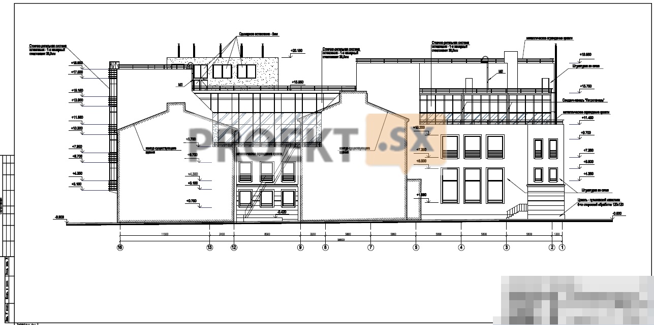
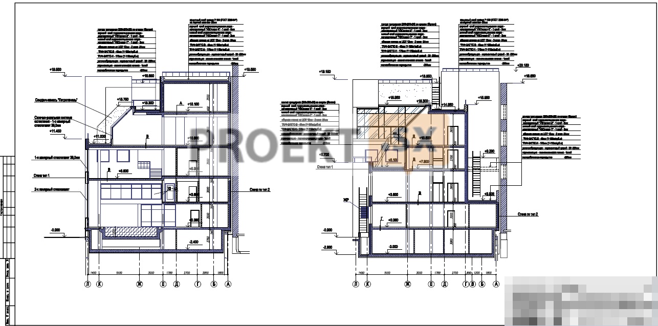
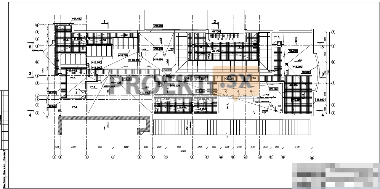
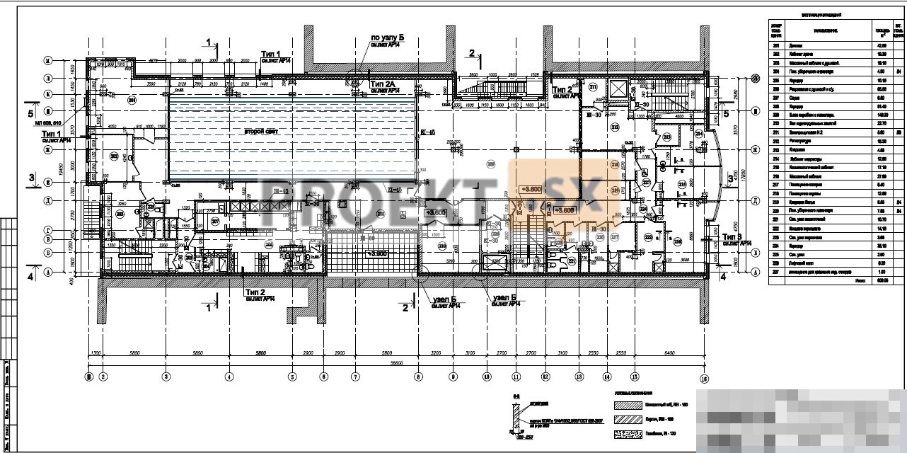
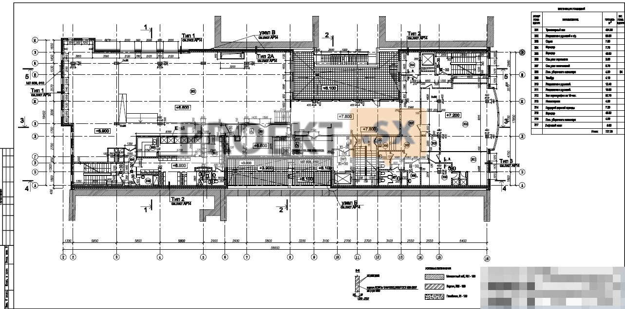
The designed building of the sports complex without stands for spectators is 2-5 storey, in the basement, rectangular in plan, with dimensions in the extreme axes of 56,6 x 19,45 m. The height of the building from the planning ground level to the top of the parapet is 20,95 m. For the relative mark of 0,000, the level of the finished floor of the first floor, corresponding to the absolute mark of 9.40, is taken. The main entrances to the building are designed from the side of the intra-block passage. In the basement at the mark - 3,000, there are designed: locker rooms with a shower and a toilet, a dining room, storage rooms for dirty and clean linen, a laundry room, a storage room for MDS and consumables, a storage room for disinfectants, a water treatment room and technical rooms (cable room, ATP station, water metering unit, ventilation chamber , emergency power supply room). The height of the premises in cleanliness (from floor to ceiling) is 2,76 and 3,06 m. nurse's room, laboratory, sales department, manager's office, cleaning equipment rooms, bathrooms. The height of the premises in cleanliness is 1 and 0,000 m. On the 0,360nd floor at around +3,0, the following are designed: a reception desk, a security room, an aerobics room, an individual training room, doctors and cosmetologists' offices, massage rooms with a shower room, a solarium, a staff room, pantries (including for cleaning equipment), bathrooms, electrical panel. The height of the premises when clean is 3,3 and 2 m. cleaning equipment room, bathrooms. The height of the premises in cleanliness is 3,600 and 3,0 m. On the 3,3th floor at the level of +3 there are designed: aerobics, individual strength training, table tennis halls, a boxing hall, a coaching room, an inventory room, wardrobes with showers, bathrooms, a cleaning equipment room. The height of the premises in cleanliness is 7,200 and 7,800 m. ). Covering (roof) - flat combined, insulated, with an internal drain. Roofing over the 3,3th floor - rolled, with a protective layer of gravel; on the balconies - paving slabs. For communication between the floors, 2 staircases of the L1 type and one of the H2 type were designed. Designed 2 elevators - 1 passenger with a carrying capacity of 630 kg and 1 passenger-and-freight (with the possibility of transporting a person on a stretcher) with a carrying capacity of 1000 kg. Finishing of external walls - plaster on a grid. Along axis 16, between the axes A-M - ventilated facade. The plinth is made of Putilov limestone. Partitions - from solid bricks with a thickness of 120, 65 mm, from aerated concrete blocks - 100-80 mm. Filling of window openings - metal-plastic window blocks with single-chamber double-glazed windows with energy-saving glass. Stained-glass windows - made of aluminum profile with single-chamber double-glazed windows with energy-saving glass. The project documentation provides for measures to ensure the accessibility of the building for people with disabilities and people with limited mobility (LGM). For access to the level 1 and 3 floors, an inclined wheelchair platform with a load capacity of 225 kg is provided. A bathroom with a universal cabin is designed on the 1st floor. There are fire safety zones on each floor. The width of the evacuation corridors is at least 1,6 m. All doors on the evacuation routes are at least 1,2 m wide.
Structural and space-planning solutions
Building responsibility level – II. The building was designed according to a mixed constructive scheme. The outer and inner walls of the basement are load-bearing, made of monolithic reinforced concrete with a thickness of 200÷250 mm. Concrete B30, W12, F150. External and internal walls - load-bearing, made of monolithic reinforced concrete 200 mm thick (with insulation (t = 150 mm), facing with bricks KORPu 1NF/100/1.2/50 (in the pool room KORPu 1NF/100/2.0/50) and plaster and multilayer , floor cutting, consisting of brickwork (t = 120 mm) of KORPu 1NF / 100 / 1.2/50 bricks, insulation (t = 140 mm), facing of KORPu 1NF / 100 / 1.2/50 bricks and plaster. Concrete B30. Columns and pylons - monolithic reinforced concrete.Maximum column spacing 6,45x5,80 m (up to 8,1 m above the pool), section of columns 300x600 and 400x400 mm in the middle axes and 250x600 in the extreme axes, concrete B30. Ceilings - beamless monolithic thickness 200 mm Concrete B30 Covering - a monolithic reinforced concrete slab 200 mm thick and, partially, in metal structures. The pool bowl with dimensions of 25,1x6,7 m is designed in monolithic reinforced concrete (B30; W8). Wall thickness - 300 mm. The bottom of the pool is a 300 mm thick beamless slab supported by 300 mm thick walls. Waterproofing is carried out according to the technology of a specialized organization. Stairs are designed from monolithic reinforced concrete, B30 concrete. The elevator shafts are designed from monolithic reinforced concrete. Wall thickness 160 and 200 mm. Concrete B30. The spatial rigidity and stability of the building is ensured by the joint work of the longitudinal and transverse load-bearing walls, the walls of the stairwells, the rigidity of the supporting nodes of the columns and the hard disks of the floors. The calculation of load-bearing structures was carried out on a computer using the SCAD Office program (version 11.1). The foundations are assumed to be piled. Piles - bored with a diameter of 500 mm and a length of ~27,0 m (abs. elev. heels -18.3). Piles are made under the protection of the casing. Concrete piles B25,W8, F150. The design load on the pile is assumed to be 100 tf according to the static sounding data, the forces in the piles according to the static calculation data are no more than 57 tf. The grillage is slab, made of monolithic reinforced concrete with a thickness of 350 mm and 600 mm in the column area, concrete class B30, W12, F150. The connection between piles and grillage is rigid. A 100 mm thick concrete preparation is provided under the foundation. The relative mark of 0,000 corresponds to the absolute mark of +9.40. In accordance with the report on engineering and geological surveys, the piles are based on light silty semi-solid loams with φ = 22, c = 0,35 kg/cm2, IL = 0,17, E = 140 kg/cm2. The maximum groundwater level is at a depth of 1,0 m. Groundwater is slightly aggressive to concrete of normal permeability in terms of the content of aggressive carbon dioxide. Soils are moderately aggressive to concrete of normal permeability in terms of sulfate content. In order to protect the concrete of underground structures, the concrete grade for water resistance is W12 with compensated shrinkage due to the addition of RD. The expected settlement of the building is not more than ~ 3,0 cm. In accordance with the technical conclusions, the following fall into the risk zone: a residential building - 18,5 meters from the designed building; residential building - 0,3 meters from the designed building; residential building - 0,2 meters from the designed building; residential building - 20,5 meters from the designed building; office building - 0,2 meters from the designed building; office building - 0,2 meters from the designed building; office building - 7,5 meters from the designed building; office building - 22 meters from the designed building; office building - 19,5 meters from the designed building. The project documentation provides for the strengthening of the roof structures of adjacent buildings prior to the start of construction according to a separate specially developed project (based on recommendations from the building survey report).